Overview
Quartz crystal resonators (Xtal) are widely used frequency components. Manufacturer datasheets typically list nominal frequency, frequency stability, operating temperature, load capacitance (load capacitance), and sometimes shunt capacitance and motional capacitance.
For example, a datasheet may specify a recommended load capacitance CL of 9 pF or 12.5 pF, a motional capacitance C1 of 6.0 fF, and a shunt capacitance Cs of 1.2 pF. What do these three capacitances represent, and how large is a motional capacitance in fF?
Load Capacitance and Shunt Capacitance
Load capacitance (CL) is the total effective capacitance seen by the crystal within the entire oscillator circuit. The value of CL determines the oscillator's operating frequency; by adjusting the load capacitance, the oscillator frequency can be tuned to the nominal value.
Manufacturers provide CL in the datasheet, typical values include 12.5 pF, 16 pF, 20 pF, and 30 pF. The relationship between CL and the resonant frequency is not linear: as shown in Figure 2, when CL decreases the frequency deviation increases; increasing CL reduces the frequency deviation.
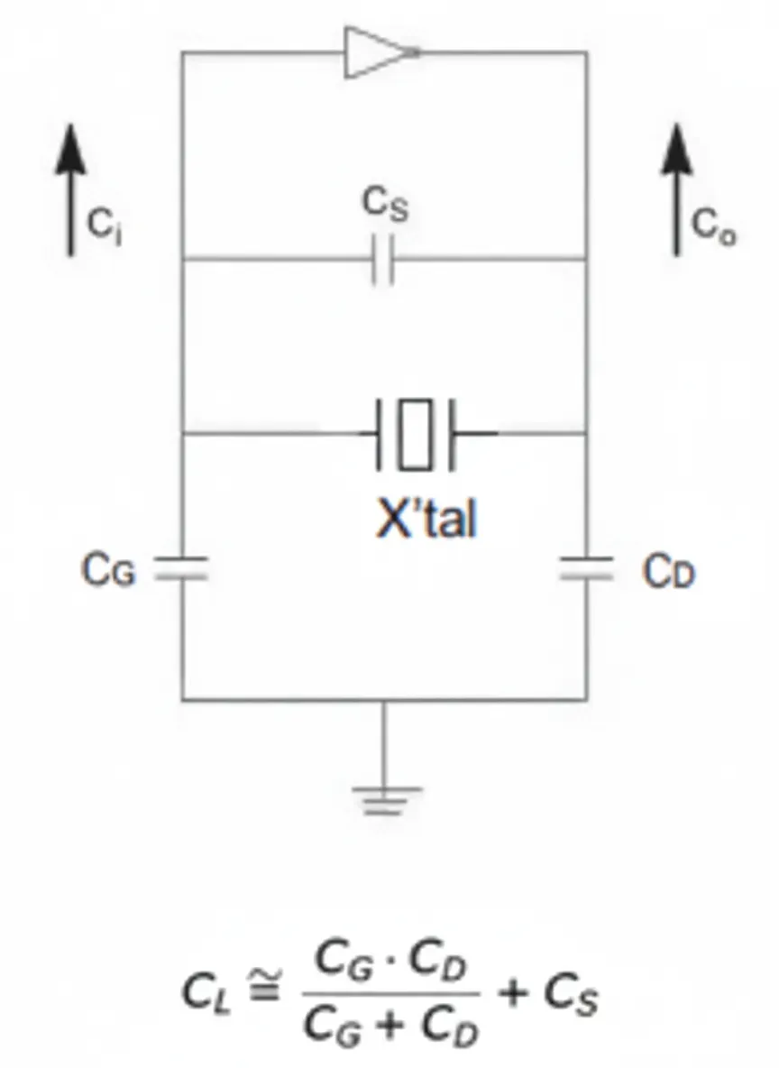
Figure 1. Crystal oscillator circuit and load capacitance definition
Load capacitance CL is composed of CG, CD, and CS. In addition to the two external capacitors in the oscillator circuit, it also includes the shunt capacitance between the crystal pins, parasitic capacitances on the IC pins, and stray capacitances from the PCB. In Figure 1, CG is the total capacitance from the oscillator input pin to ground (including the external CG capacitor and the small capacitance of the crystal pin); CD is the total capacitance from the oscillator output pin to ground (including the external CD capacitor and the small capacitance of the crystal pin); CS is the total shunt (parasitic) capacitance.
Shunt capacitance (CS) is sometimes called parallel capacitance in datasheets and is typically in the range of 0.2 to 8 pF. The IC pin capacitances Ci and Co can usually be found in the IC datasheet. Compared with CS, Ci and Co are much smaller and can often be ignored. In practice, external capacitors CG and CD are calculated as follows. To keep the crystal load balanced, CG = CD is usually required, so the formula in Figure 2 becomes:
CL = CG/2 + CS = CD/2 + CS
Using CL = 12.5 pF and CS = 1.2 pF from the datasheet example,
CG/2 = CD/2 = CL - CS = 12.5 pF - 1.2 pF = 11.3 pF,
so CG = CD = 22.6 pF.
Note that many modern ICs include internal compensation capacitances. If an IC datasheet specifies a recommended load capacitance, designers can generally select a crystal that matches that load and may not need additional external capacitors. However, due to uncertainties in parasitic capacitances, it is good practice to leave pads for CG/CD on the board.
Motional Capacitance and the fF Unit
In addition to load and shunt capacitances, crystal characteristics include a capacitive parameter called motional capacitance. Some manufacturers provide this parameter; its magnitude is typically a few femtofarads (fF). The femtofarad is a very small capacitance unit:
1 fF = 10^-15 F = 10^-3 pF = 10^-6 nF = 10^-9 μF
Given that the motional capacitance is on the order of a few fF, its effect on the load capacitance is negligible. This is why many crystal manufacturers do not provide the motional capacitance in the datasheet.