NTC Thermistor Technology and Key Characteristics
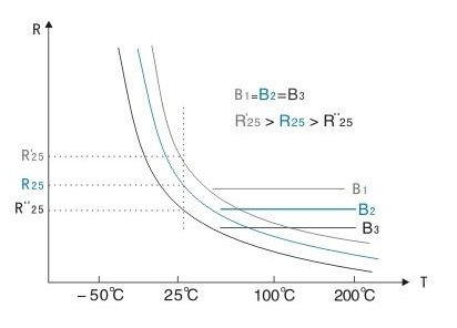
Negative Temperature Coefficient (NTC) thermistors are among the most widely used temperature sensors in electronics due to their high sensitivity, low cost, and compact size. An NTC thermistor is a polycrystalline ceramic semiconductor whose resistance decreases exponentially with increasing temperature. The resistance-temperature relationship is typically modeled by the Steinhart-Hart equation or the simpler beta (B) parameter model.
Critical parameters include:
- Beta Value (B25/85): Indicates temperature sensitivity. Higher B values provide greater resistance change per degree Celsius.
- Resistance at 25.C (R25): Standard reference value, commonly available from 1 kOhm to 100 kOhm.
- Dissipation Constant (d): Measures self-heating effect in mW/.C.
- Thermal Time Constant (t): Time required to reach 63.2% of a temperature change.
- Tolerance and Stability: Initial accuracy and long-term drift under operating conditions.
Unlike RTDs or thermocouples, NTC thermistors offer very high sensitivity in the -50 .C to +150 .C range but exhibit strong non-linearity, which must be addressed in circuit design.
Primary Applications and Use Cases
NTC thermistors are extensively used for:
- Temperature compensation in crystal oscillators and power amplifiers
- Over-temperature protection in power supplies, motor drives, and battery packs
- Inrush current limiting (power thermistors)
- Liquid and air temperature sensing in HVAC and medical equipment
- Thermal management in IGBT modules, SiC devices, and other power semiconductors
In high-power systems, they are frequently placed near heat-generating components such as IGBTs, MOSFETs, or power transformers to provide real-time junction temperature estimation or protection triggering.
Circuit Design Considerations and Engineering Challenges
Designing with NTC thermistors requires careful attention to several factors:
Linearization Techniques
The strongly non-linear R-T curve is often linearized using parallel or series resistors, or through software compensation in microcontroller-based systems. The choice affects accuracy, resolution, and ADC dynamic range.
Self-Heating Effects
Excitation current through the thermistor generates heat. In high-precision applications, excitation must be limited to a few microamps to minimize measurement error. The dissipation constant becomes a critical design parameter.
Noise and Filtering
In electrically noisy environments (common near power converters), proper filtering and shielding of the sense lines are required to prevent false readings.
Failure Modes
NTC thermistors can fail short or open. Safety-critical systems often implement dual-sensor redundancy or use the thermistor in a way that open-circuit failure triggers a safe shutdown.
Manufacturing and Reliability Challenges
Industrial and automotive applications subject NTC thermistors to thermal cycling, vibration, and humidity. Reliable performance depends on robust mechanical mounting, consistent thermal coupling to the heat source, and protection against moisture ingress. In surface-mount designs, solder joint reliability under thermal expansion mismatch is a recurring concern.
Materials, PCB Design, and Thermal Integration
PCB design significantly influences measurement accuracy and response time. Key considerations include:
- Thermal Coupling: The thermistor should be placed as close as possible to the heat source (e.g., near IGBT baseplate or power resistor). Thermal vias, copper pours, and sometimes metal-core substrates (IMS) improve heat transfer.
- Trace Routing: Kelvin (four-wire) sensing is recommended for high-accuracy designs to eliminate trace resistance errors.
- Material Selection: High-Tg laminates and low-CTE materials reduce stress on SMD thermistors during temperature cycling. For extreme environments, flexible circuits (FPC) or ceramic substrates may be preferred.
- Self-Heating Mitigation: Careful layout to minimize localized heating from nearby power components or high-current traces.
- EMI Immunity: Shielded traces or ground planes are essential when routing thermistor signals near high dv/dt switching nodes.
In power electronics assemblies involving IGBTs or other high-power devices, the PCB often serves as both the electrical interconnect and the thermal sensing platform, making material engineering and fabrication quality critical to overall system reliability.
Industry Trends
Demand for higher accuracy, faster response, and better long-term stability is driving adoption of NTC thermistors with tighter tolerances and improved coatings. Integration with power modules (including IGBT and SiC modules) is increasing, requiring closer collaboration between module manufacturers, PCB fabricators, and system designers. Digital temperature sensors are replacing NTCs in some applications, but NTC thermistors retain strong advantages in cost, size, and high-temperature capability.
The Role of PCB Technologies in NTC Thermistor Systems
Effective NTC thermistor performance depends heavily on supporting PCB fabrication and assembly processes. Precise control of copper weight, thermal via density, and dielectric thickness directly affects thermal response time and measurement accuracy. High-reliability PCB materials with stable mechanical properties across wide temperature ranges minimize stress on the sensor and reduce long-term drift.
From a manufacturing perspective, consistent solder joint formation, proper pad design, and controlled reflow profiles are essential to prevent mechanical damage to the ceramic element. These engineering considerations - from material selection to thermal design and assembly quality - determine whether an NTC-based temperature sensing solution achieves the reliability and accuracy demanded in modern power electronics and industrial systems.
Optional FAQ
Q1: What does the beta (B) value represent in an NTC thermistor?
A1: The beta value indicates the thermistor's sensitivity to temperature change. Higher beta values produce a steeper resistance-temperature curve, offering greater resolution within a specific temperature range.
Q2: How can self-heating effects be minimized?
A2: Use the lowest practical excitation current (typically <100 uA for precision sensing), select a thermistor with a high dissipation constant, and ensure good thermal coupling to the measured surface.
Q3: Why is PCB material choice important for NTC thermistor accuracy?
A3: High-Tg laminates, stable dielectric constants, and optimized copper structures reduce thermal stress, warpage, and heat spreading variations that can introduce measurement errors or long-term drift in temperature sensing circuits.