Overview of Power Factor Correction (PFC)
Power Factor Correction (PFC) is essential in modern AC-DC power supplies to improve power factor close to unity, minimize phase differences between voltage and current, and reduce harmonic distortion. Compliance with standards like IEC 61000-3-2 drives its adoption across consumer electronics, industrial control, LED lighting, new energy systems, and telecommunications equipment.
Effective PFC not only meets regulatory requirements but also enhances energy efficiency, reduces stress on the grid, and improves overall system reliability. In power supply design, the choice of topology and operating mode significantly impacts efficiency, component stress, thermal management, and electromagnetic compatibility (EMC).
Single-Stage vs. Interleaved PFC Topologies
Single-stage PFC typically employs one switching device (e.g., MOSFET), a boost inductor, and diodes. The inductor current forms triangular waveforms synchronized with the switching cycle, with the average current shaped to follow the input voltage sine wave.
Interleaved PFC uses two (or more) parallel channels phase-shifted by 180 degrees, overlapping current triangles. This approach offers several advantages:
- Reduced input current ripple and higher effective ripple frequency, allowing smaller input filters.
- Distributed switching and conduction losses, easing thermal design and improving reliability.
- Better scalability for higher power levels.
Interleaved designs mirror multi-phase DC/DC converters and are preferred in medium-to-high power applications where size, efficiency, and thermal performance are critical.
Boundary Conduction Mode (BCM) vs. Continuous Conduction Mode (CCM)
PFC controllers primarily operate in two modes:
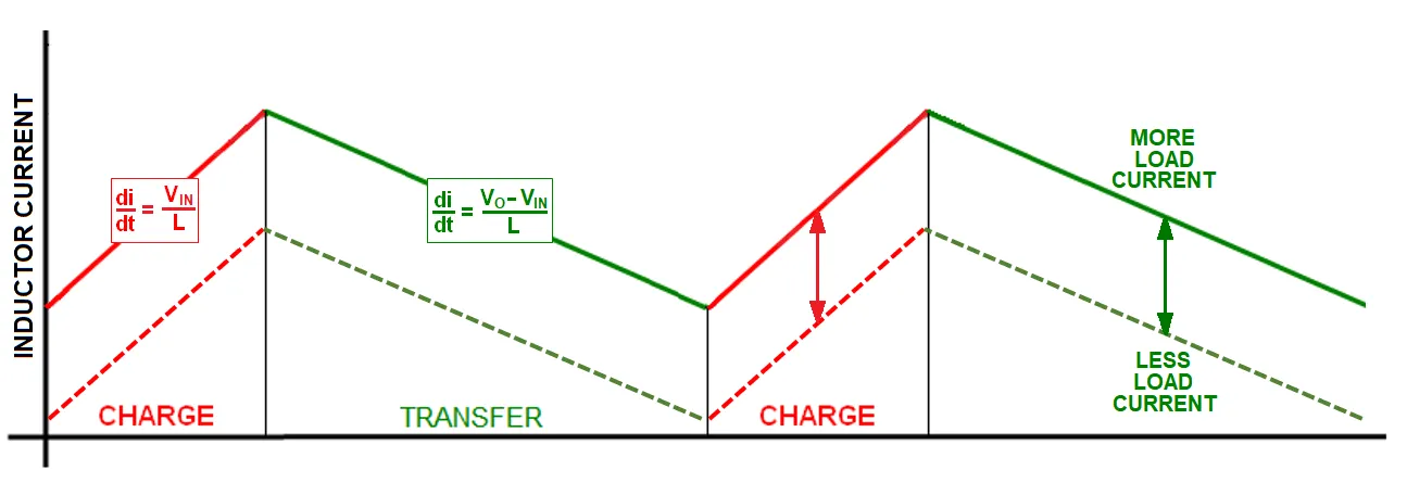
Boundary Conduction Mode (BCM), also known as Critical Conduction Mode, switches the transistor when the inductor current reaches zero. This eliminates diode reverse-recovery losses but results in higher peak currents, variable switching frequency, and increased stress on the inductor and switches.
Continuous Conduction Mode (CCM) maintains continuous inductor current flow throughout the switching cycle. It features lower peak currents, fixed-frequency operation (often easier for filtering), but introduces significant diode reverse-recovery current when the switch turns on, leading to higher switching losses and noise.
Mode Selection Considerations:
- BCM: Suitable for lower-to-medium power applications (e.g., LCD TV power supplies) where zero-current switching reduces losses and simplifies control.
- CCM: Preferred for higher power levels due to lower ripple currents and better suitability for fixed-frequency designs.
Higher-power systems often combine interleaved topologies with CCM for optimal performance.
Diode Selection Strategies for Efficiency Optimization
Diode characteristics - forward voltage drop (VF) and reverse-recovery time (trr) - play a decisive role in PFC efficiency, varying by operating mode.
BCM PFC: Prioritizing Low VF
In BCM, the diode conducts from peak current down to zero each cycle. Conduction losses dominate, making low VF critical. Simulations on a single-stage BCM PFC (e.g., LCD TV module) showed a low-VF diode (VF approx 1.25V) achieving significantly lower power loss (~0.23W average) compared to a faster trr but higher-VF diode (~0.41W), despite similar other specs.
Recommendation: Select ultrafast or Schottky diodes with minimal VF for BCM PFC to minimize conduction losses. Reverse-recovery effects are negligible due to zero-current turn-off.
CCM PFC: Prioritizing Low trr
In CCM, the diode is forcibly commutated, generating substantial reverse-recovery current (IRR) that stresses the MOSFET during turn-on. This leads to higher switching losses. Efficiency comparisons at 300W, 200kHz showed diodes with lower trr (20-25ns) delivering 93-94% efficiency versus ~89% for a higher trr device, with VF having minimal impact.
Recommendation: Choose fast-recovery diodes (FRDs) with the lowest possible trr for CCM PFC. This reduces reverse-recovery-induced losses and EMI.
PCB Design and Manufacturing Considerations for PFC Circuits
Power electronics circuits, particularly PFC stages, impose stringent demands on PCB design and fabrication:
- Thermal Management: High-current paths require thick copper (2oz+), wide traces, and thermal vias. Proper component placement and heatsinking are essential for MOSFETs, diodes, and inductors.
- Signal Integrity and Layout: Minimize loop areas for high di/dt paths to reduce EMI. Separate power and control grounds; use Kelvin connections for sensing.
- High-Frequency Considerations: In CCM with higher switching frequencies, controlled impedance and careful routing prevent parasitic inductance issues. Interleaved designs may require symmetric layouts.
- Reliability Enhancements: High-Tg materials, conformal coatings, and robust assembly processes improve performance in harsh environments (e.g., industrial control or automotive).
- Component Integration: Power supply PCBs often integrate controllers, drivers, and sensing circuitry. High-density interconnect (HDI) or multilayer boards support compact designs while maintaining isolation and creepage distances.
Manufacturing expertise in power electronics ensures consistent quality, especially for high-power, high-voltage applications where material selection and process control directly affect long-term reliability and efficiency.
Industry Applications and Trends
PFC is ubiquitous in LED drivers, industrial power supplies, EV chargers, renewable energy inverters, and data center equipment. Trends toward higher efficiency (e.g., Titanium-level PSUs), wide-bandgap semiconductors (GaN/SiC), and digital control are pushing boundaries in BCM/CCM implementations.
For electronics manufacturers, understanding these modes informs better system-level design, from power stage optimization to overall thermal and EMC performance.
Frequently Asked Questions
Q1: What is the main difference between BCM and CCM in PFC?
A1: BCM switches at zero inductor current (no reverse recovery, variable frequency, higher peaks); CCM maintains continuous current (fixed frequency, lower ripple, but requires fast diodes to manage reverse recovery).
Q2: When should interleaved PFC be used?
A2: Interleaved topologies are ideal for higher power levels to reduce ripple, distribute losses, and simplify filtering and thermal management.
Q3: How does diode selection impact PFC efficiency?
A3: In BCM, prioritize low VF to reduce conduction losses. In CCM, prioritize low trr to minimize switching losses from reverse recovery.