Overview of Quartz Crystal Oscillators
Quartz crystal oscillators (XOs) provide the high frequency stability essential for modern electronics. While LC or RC resonant networks offer basic oscillation, their stability is limited by temperature, load, and supply variations. Quartz crystals leverage the piezoelectric effect - where mechanical deformation generates charge and applied voltage produces vibration - to serve as precise frequency-determining elements.
This piezoelectric behavior enables mechanical resonance that replaces traditional LC tanks, delivering superior accuracy and stability for timing in microprocessors, communication systems, and precision instruments.
Quartz Material Properties and Crystal Blanks
Quartz dominates oscillator applications due to its excellent mechanical strength, chemical stability, and low thermal expansion. Manufacturers cut quartz into thin wafers (blanks) with tightly controlled dimensions and thickness, which directly determine the fundamental resonant frequency. Metallized electrodes on parallel surfaces enable electrical connections.
The frequency is inversely proportional to the blank thickness. Crystal cuts (e.g., AT-cut for temperature stability) influence vibration modes, frequency range, and performance over temperature. Variations in cut angle or uniformity can introduce harmonics or overtones, which designers must manage for consistent operation.
Equivalent Circuit and Resonance Behavior
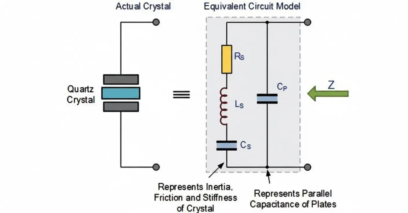
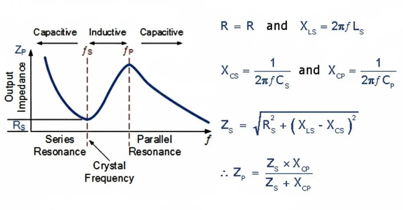
A quartz crystal's electrical behavior is modeled as a series RLC branch (motional resistance Rs, inductance Ls, capacitance Cs) in parallel with shunt capacitance Cp (from electrodes and leads).
- Series resonance (fs): Occurs when Ls and Cs cancel, yielding minimum impedance (approx Rs).
- Parallel resonance (fp): Involves interaction with Cp, producing maximum impedance at a slightly higher frequency.
The narrow separation between fs and fp, combined with extremely high Q factors (typically 20,000-200,000 vs. <1,000 for LC circuits), enables exceptional frequency stability. Crystals operate near series resonance in many circuits but can use parallel mode depending on the topology.
Resonant Frequency Expressions (simplified):
- fs approx 1 / (2pi sqrt(Ls x Cs))
- fp is determined by the series branch interacting with Cp.
High Q minimizes energy loss, supporting precise oscillation even under varying conditions.
Oscillator Circuits and Operating Modes
Common topologies include:
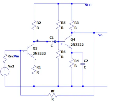
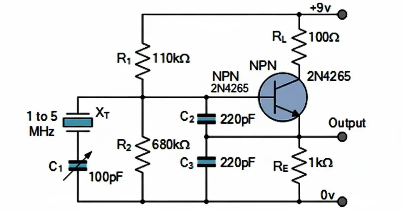
- Colpitts Crystal Oscillator: Replaces the LC tank with a crystal in a common-collector or similar configuration. Feedback capacitors divide the signal while limiting drive level to prevent crystal overstress.
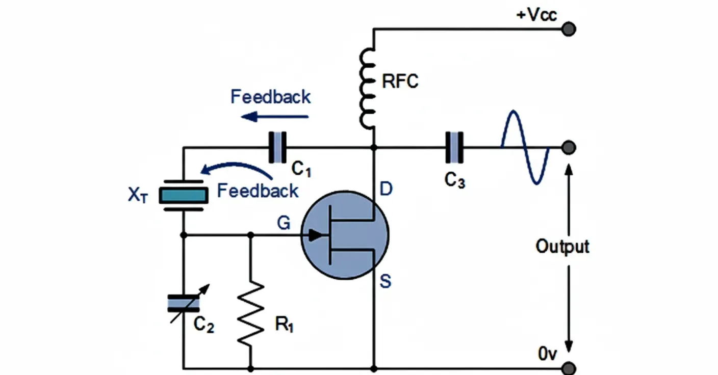
- Pierce Oscillator: Popular for its simplicity, often using inverters or JFETs. It operates at series resonance and requires minimal components, making it ideal for low-power designs like watches and microcontrollers.
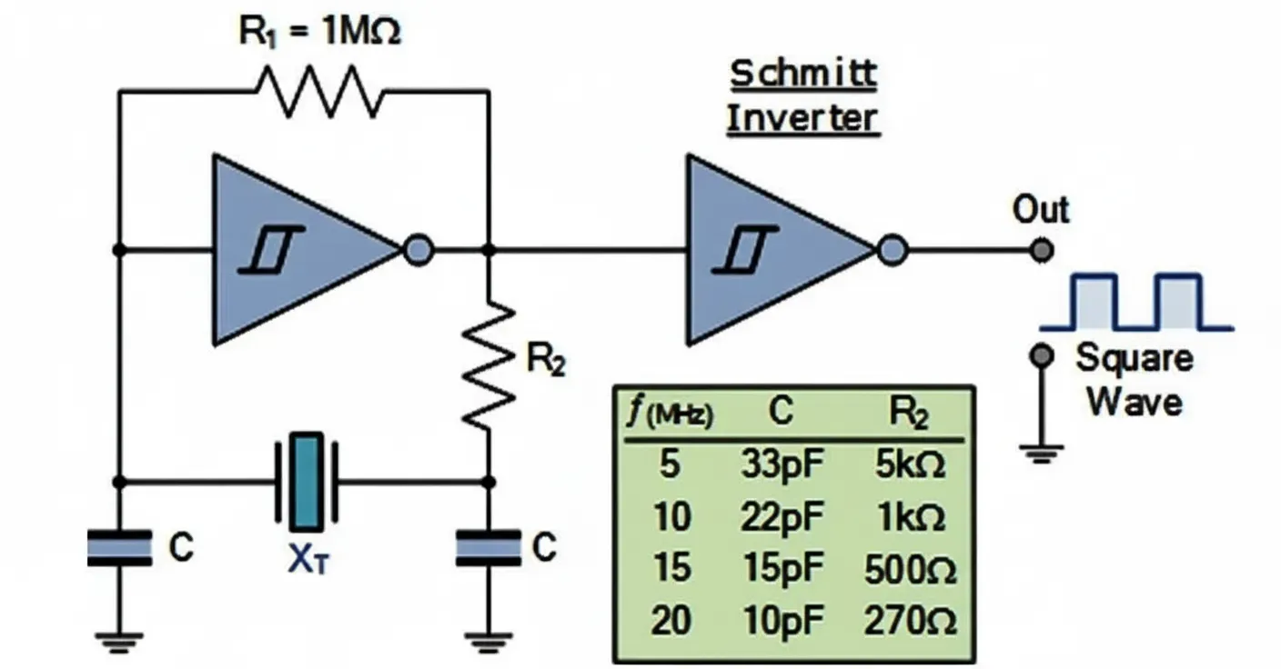
- CMOS Crystal Oscillators: Use Schmitt-trigger inverters with load capacitors and a drive-limiting resistor. These produce square-wave outputs suitable for digital clocks.
Oscillators can run in fundamental mode or overtone/harmonic modes (odd multiples preferred for overtones). Frequency range typically spans 32 kHz to over 100 MHz, with higher frequencies often requiring specialized cuts or surface-mount packages.
Applications in Electronics
Quartz oscillators serve as clock sources for microprocessors, microcontrollers, and digital systems, where they define instruction timing and synchronization. A typical MCU setup uses the crystal plus two load capacitors (15-33 pF) connected to OSC1/OSC2 pins.
Broader uses include:
- Telecommunications and RF systems for frequency synthesis and stable carriers.
- Automotive electronics for engine control, infotainment, and ADAS timing.
- Industrial control, medical devices, and aerospace for precision synchronization.
- Consumer electronics, wearables, and IoT for low-power real-time clocks.
PCB Design Considerations for Crystal Oscillators
Successful integration demands careful layout to preserve stability and minimize noise:
- Place the crystal and load capacitors as close as possible to the IC oscillator pins (ideally <5-10 mm trace length, shorter for high frequencies) to reduce parasitic inductance and capacitance.
- Use short, direct traces without right-angle bends; prefer 45 degree or curved routing. Route traces differentially where possible and avoid crossing other signals.
- Implement a solid ground plane beneath the oscillator section with high via density for shielding. Consider a guard ring around the circuit. Avoid routing under the crystal to minimize parasitic effects.
- Isolate from noisy components like switching regulators or high-speed lines. Minimize vias in the oscillator loop.
- Account for PCB parasitics in load capacitance calculations. In high-density or flex designs, material choice (e.g., low-loss dielectrics) and controlled impedance become critical.
These practices reduce EMI, crosstalk, and frequency pulling, ensuring reliable operation.
Manufacturing and Reliability Challenges
From a production standpoint, quartz crystals introduce specific considerations:
- Drive Level Management: Excessive power can cause frequency shifts or crystal damage. Designers specify maximum drive levels (often in uW or mW).
- Temperature and Aging: Frequency drifts with temperature (minimized by AT-cuts or TCXOs) and long-term aging. Selection must match operating environment.
- Mechanical Sensitivity: Crystals are vibration- and shock-sensitive; secure mounting and proper encapsulation are essential in automotive or industrial PCBs.
- Sourcing and Consistency: Tight tolerance blanks (ppm-level) require reliable supply chains. Variations in cut or metallization affect yield.
- Assembly: SMT crystals demand precise reflow profiles to avoid thermal stress. Inspection for solder joint integrity is key for high-reliability assemblies.
PCB fabricators support these by offering high-precision multilayer boards, impedance control, and advanced materials for thermal management and signal integrity in timing-critical designs.
Industry Trends and Future Outlook
Demand grows for higher stability in 5G, automotive radar, and edge AI applications. While traditional quartz remains dominant for cost-performance balance, alternatives like MEMS oscillators emerge for smaller size and shock resistance. Hybrid approaches and integrated timing solutions continue to evolve, but quartz's high Q and maturity ensure its central role. Trends emphasize better thermal compensation, lower power, and seamless integration into dense, high-speed PCBs.
Supporting Precision Timing Through Advanced Electronics Manufacturing
In electronic system design, reliable crystal oscillator performance depends heavily on the supporting PCB platform. High-quality fabrication ensures consistent dielectric properties, precise trace geometry, and robust layer registration - factors that directly impact parasitic effects and signal integrity around sensitive timing circuits. Flexible circuits (FPCs) and high-density interconnect (HDI) technologies further enable compact layouts in space-constrained applications like wearables or automotive modules, while advanced assembly processes maintain the mechanical and thermal integrity required for long-term frequency stability.
Effective collaboration between circuit designers and manufacturing partners optimizes these elements, from material selection to final testing, delivering systems that meet stringent industrial and reliability requirements.
Optional FAQ Section
Q1: What is the difference between series and parallel resonance in quartz crystals?
A1: Series resonance offers low impedance at fs; parallel resonance provides high impedance at the slightly higher fp. Circuit topology determines the operating mode.
Q2: Why is PCB layout critical for crystal oscillators?
A2: Poor layout introduces parasitics, noise, and EMI that degrade frequency stability and increase jitter. Short traces, grounding, and isolation are essential.
Q3: How do I select load capacitors for a crystal?
A3: Match the crystal's specified load capacitance, accounting for IC input capacitance and PCB strays. Typical values are 15-33 pF; consult the datasheet and manufacturer recommendations.