Resistors are fundamental passive components whose electrical characteristics, physical construction, and placement on printed circuit boards directly influence circuit performance, thermal behavior, signal integrity, and long-term reliability. Proper selection and PCB implementation require understanding resistance values, tolerances, power dissipation, parasitic effects, and manufacturing constraints.
Resistor Fundamentals and PCB Implications
Every resistor opposes current flow according to Ohm's law, but on a PCB the chosen resistance value, tolerance, and temperature coefficient must align with the board's operating environment. Trace resistance, via resistance, and copper thickness can add unwanted series resistance, especially in precision or high-current paths. Low-inductance, low-capacitance resistor placement is essential for high-speed or RF circuits, where even small parasitic inductance from lead length or trace routing can degrade performance.
Resistor Color Bands and Identification on PCBs
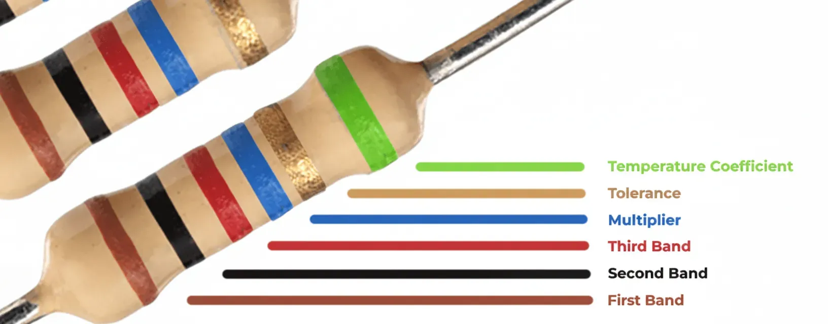
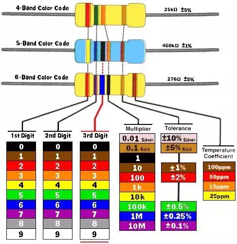
Color bands provide a quick visual method to read resistance value, tolerance, and sometimes temperature coefficient on through-hole resistors. On densely populated PCBs, however, color coding becomes impractical once components are mounted and coated. Engineers therefore rely on part numbers, silkscreen markings, or automated optical inspection during manufacturing. When color bands are used for incoming inspection or rework, consistent lighting and orientation standards on the assembly line help prevent misreads that could lead to incorrect component placement.
Manufacturing Types and Material Choices
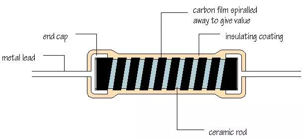
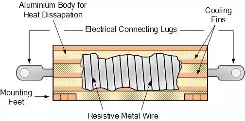
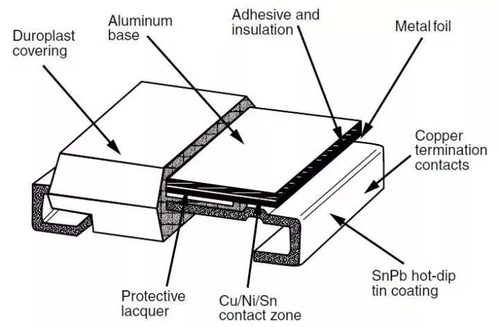
Resistors are produced as carbon composition, carbon film, metal film, metal oxide, wire-wound, and thick- or thin-film chip types. Each construction offers different trade-offs in tolerance, temperature coefficient, noise, and power handling—factors that translate directly into PCB material and layout decisions. Metal-film and thin-film chip resistors provide excellent stability and low noise, making them suitable for precision analog sections on multilayer boards. Wire-wound resistors handle high power but introduce inductance that must be considered in switching circuits; they often require larger copper pours or heatsinking vias. Thick-film chip resistors are cost-effective for general-purpose use but exhibit higher noise and poorer temperature coefficients than thin-film alternatives.
Common Resistor Types and Their PCB Characteristics
- Carbon film: Economical, moderate stability; suitable for non-critical digital pull-ups where cost outweighs precision.
- Metal film: Low temperature coefficient, low noise; preferred for analog signal paths and feedback networks.
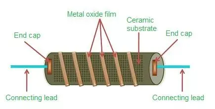
- Metal oxide: Higher power capability and flame-retardant properties; useful near power stages.
- Wire-wound: High power and pulse handling; requires careful thermal management and spacing from sensitive traces.
- Chip resistors (SMD): Dominant in modern SMT assemblies; available in standard sizes (0402, 0603, 0805, etc.) that dictate minimum trace widths and pad geometries.
Practical Resistor Selection Criteria for PCB Designs
Selection begins with required resistance, tolerance, and power rating, then expands to temperature coefficient, voltage coefficient, noise, and long-term drift. On the PCB, derate power by at least 50 % and account for local ambient temperature rises caused by nearby components. Choose tolerances tight enough for the application but not so tight that yield drops during manufacturing. For high-reliability boards, specify resistors with established reliability grades and verify that the chosen package matches the PCB's copper weight and thermal relief requirements.
Potentiometers in PCB Applications
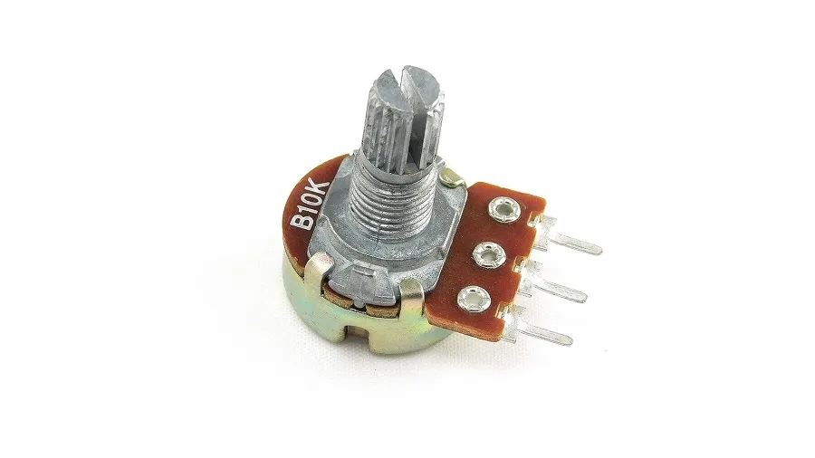
Potentiometers provide adjustable resistance for calibration, gain setting, or user controls. Trimmer potentiometers are typically surface-mount or through-hole devices placed on the multilayer PCB for factory calibration, while panel-mount types require additional mechanical mounting and longer leads that increase inductance. On the board, place trimmers away from heat sources and vibration-prone areas; use multi-turn types for fine adjustment and lock them after calibration to prevent drift. Consider wiper noise and contact resistance in precision circuits, and route wiper traces with minimal length to reduce pickup.
Pull-Up and Pull-Down Resistors: Impact on PCB Drive Strength and Signal Integrity
Pull-up and pull-down resistors set default logic levels and prevent floating inputs. Their value must balance static power consumption against the drive strength of the connected output and the input capacitance of the load. On the PCB, place these resistors close to the driven device to minimize stub length and reduce ringing. Weak pull resistors can allow noise coupling into high-impedance nodes; stronger values improve noise immunity but increase power dissipation and may require wider traces or additional copper for heat spreading. In high-speed designs, account for the time constant formed by the pull resistor and trace capacitance when calculating rise/fall times.
PCB Layout Best Practices for Resistors
- Keep resistor leads or pads as short as possible to minimize parasitic inductance and capacitance.
- Use thermal reliefs on high-power resistors to prevent excessive heat transfer into the board during soldering while still providing adequate heat sinking.
- Route sensitive analog signals away from power resistors to avoid thermal EMF and noise.
- Specify appropriate solder mask and surface finish for high-voltage or high-reliability applications.
- Place resistors in consistent orientation during layout to simplify automated assembly and inspection.
Conclusion
Effective resistor selection and implementation on PCBs require balancing electrical specifications with thermal, mechanical, and manufacturing realities. By applying the principles of value identification, type selection, power derating, and optimized layout, engineers achieve stable performance, reduced noise, and higher production yields across automotive, industrial, medical, and consumer electronics. Early involvement of an experienced PCB manufacturer ensures that material choices, copper weights, via strategies, and assembly processes fully support the intended resistor performance throughout the product lifecycle.