Overview
Digital potentiometers (digiPOTs) are versatile components widely used in analog signal processing, filtering, and waveform generation. For applications requiring adjustable frequency sine waves, a programmable oscillator provides flexibility during development and testing. This design uses digiPOTs to independently tune both oscillation frequency and amplitude in a classic Wien bridge topology.
Circuit Description
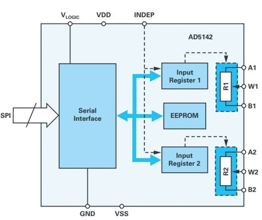
The circuit is based on a diode-stabilized Wien bridge oscillator using a precision rail-to-rail op-amp (e.g., ADA4610-1) and a dual-channel digiPOT (e.g., AD5142 with SPI interface, 256 positions, available in 10 kΩ or 100 kΩ versions). The AD5142A I2C variant can be substituted. The Wien bridge consists of:
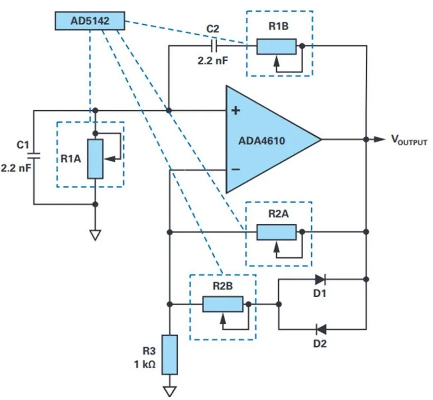
- Positive feedback network (series R1-C1 and parallel R1-C2 paths) forming a bandpass response.
- Negative feedback through R2 and parallel diodes (or equivalent resistance) for amplitude stabilization.
The digiPOT replaces fixed resistors, allowing digital control of R1 (frequency) and R2 (amplitude). SPI (or I2C) programming sets the wiper positions.
Operation and Tuning Equations
The oscillation frequency is determined by the RC network in the positive feedback path: f = 1 / (2 * pi * R * C), where R represents the programmable resistance from the digiPOT (R = D * R_AB / 256, with D as the decimal code and R_AB the total end-to-end resistance). For stable oscillation, the loop gain must satisfy the Barkhausen criterion (loop gain approx 1 with 0 degree phase shift). The negative feedback gain is set slightly above 2 to ensure startup, with diodes providing nonlinear stabilization to prevent saturation. Amplitude is primarily controlled by the negative feedback resistor R2: Amplitude tuning is independent of frequency once R1 is set. Shorting part of R2B yields approx +/-0.6 V output; proper adjustment balances the loop for stable sinusoidal output.
Performance Considerations
- Frequency Range: With a 10 kΩ digiPOT, examples include approx 8.8 kHz (8 kΩ), 17.6 kHz (4 kΩ), and up to approx 102 kHz (670 Ω), with errors typically +/-3%. Higher frequencies (e.g., 200 kHz) may see approx 6% error due to component tolerances and op-amp limitations.
- DigiPOT Bandwidth: Higher resistance settings reduce bandwidth; verify against application requirements.
- Programming Considerations: Sequential programming of channels can create transient states. Use daisy-chain capable devices (e.g., AD5204) for simultaneous updates in sensitive applications.
- Distortion and Stability: Diode stabilization keeps THD low. Power supply decoupling and layout are critical for clean output.
PCB Design and Layout Guidelines
To achieve stable, low-distortion performance:
- Component Placement: Keep RC networks and digiPOT close to the op-amp to minimize parasitics and stray capacitance.
- Grounding: Use a solid ground plane with star grounding for analog sections to reduce noise.
- Power Supply: Decouple op-amp and digiPOT supplies with ceramic capacitors (0.1 uF + 10 uF) placed near pins. Consider separate analog/digital supplies if SPI control is noisy.
- Trace Routing: Short, matched traces for feedback paths. Avoid crossing digital control lines over sensitive analog nodes.
- Thermal and Mechanical: Ensure good thermal dissipation for the op-amp; vibration-resistant assembly for industrial/test equipment use.
- Manufacturing: Precision resistors/capacitors (1% tolerance recommended) and controlled impedance if extending to higher frequencies. Automated assembly and inspection improve repeatability.
Conclusion and Applications
This simple programmable Wien bridge oscillator offers an easy-to-implement solution for generating tunable sine waves in test and measurement, audio, or sensor excitation applications. Digital control via SPI/I2C integrates seamlessly with microcontrollers for automated test setups. The design highlights the synergy between precision analog circuits and digital interfaces, with careful PCB layout being key to realizing theoretical performance in real hardware.
FAQ
Q1: How is frequency adjusted in this Wien bridge design?
A1: By programming the digiPOT resistance in the RC feedback network (R1). Amplitude is independently tuned via the negative feedback resistor (R2).
Q2: What op-amp and digiPOT are recommended?
A2: ADA4610-1 (or similar precision rail-to-rail) and AD5142/AD5142A dual digiPOT.
Q3: Why is PCB layout important for oscillator stability?
A3: It minimizes parasitic capacitance/inductance, reduces noise coupling, and ensures consistent RC time constants for accurate frequency and low distortion.