The Silicon Controlled Rectifier (SCR) in Power Electronics
The Silicon Controlled Rectifier (SCR), commonly known as a thyristor, remains one of the most robust and widely used power semiconductors in industrial control, motor drives, heating systems, and medium-power AC/DC conversion. Proper SCR circuit design requires deep understanding of device characteristics, precise triggering techniques, robust protection circuits, and careful integration with supporting PCB technologies.
Thyristor Technology and Operating Principles
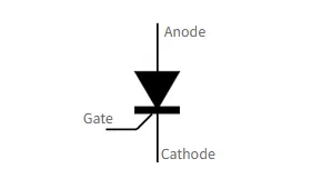
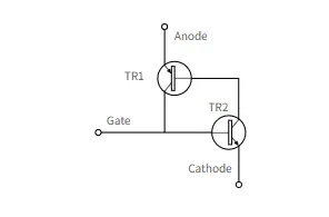
A thyristor is a four-layer (P-N-P-N) regenerative semiconductor switch. Once triggered via the gate terminal, it latches into conduction and remains on until the anode current falls below the holding current, typically at AC zero-crossing. Key parameters include forward blocking voltage, peak repetitive reverse voltage (PRV), dv/dt rating, di/dt rating, gate trigger current (Igt), and latching current (Il).
Unlike transistors, thyristors cannot be turned off via the gate. This fundamental characteristic dictates circuit topology and places strict requirements on both electrical and thermal design.
Core Applications and Circuit Topologies
SCRs are commonly found in:
- Industrial AC power control (soft starters, heaters, lighting)
- DC motor drives and battery chargers
- Crowbar protection circuits
- HVDC transmission and static switches
- Phase-controlled rectifiers
Common circuit configurations include single-phase and three-phase controlled rectifiers, AC voltage regulators, and zero-crossing switches. Each topology presents different challenges regarding commutation, harmonic generation, and EMI.
Design Considerations and Protection Strategies
Successful SCR circuit design must address several critical engineering challenges:
Gate Triggering Circuits
Gate drive must provide sufficient current (typically 2-5x Igt) with fast rise time while maintaining isolation. Transformer-coupled, optocoupler, or direct drive methods each have trade-offs in noise immunity and timing precision. Pulse transformers are still widely used in industrial systems due to their robustness.
dv/dt and di/dt Protection
Thyristors are sensitive to rapid voltage rise (dv/dt) which can cause false triggering, and rapid current rise (di/dt) which can cause localized hot spots. RC snubber networks across the anode-cathode are essential. Component values must be carefully calculated based on system voltage, load inductance, and device specifications.
Overvoltage and Overcurrent Protection
MOVs (metal oxide varistors), fast-acting fuses, and crowbar circuits are typically employed. Coordination between protection devices and the SCR's surge current rating is critical for long-term reliability.
Thermal Management
Junction temperature must remain within safe limits. Heat sink design, thermal interface materials, and airflow are key. Many designs incorporate temperature sensing directly on the PCB near the SCR mounting area.
Manufacturing and Reliability Challenges
SCR circuits in industrial environments face severe operating conditions including wide temperature swings, high vibration, dust, and electrical noise. Manufacturing must ensure consistent solder joint integrity, especially for large TO-247, TO-218, or press-pack packages. Thermal cycling can cause fatigue in both the device and the PCB, making material selection and assembly process control critical.
Materials, PCB Design, and System Integration
PCB design plays a decisive role in SCR circuit reliability. Key considerations include:
- High-current layout: Wide copper traces or bus bars are required to handle RMS currents often exceeding 50 A. Copper thickness of 2 oz to 6 oz is common.
- Creepage and clearance: High-voltage designs must meet safety standards for pollution degree and working voltage.
- Thermal solutions: Thermal vias, copper pours, and sometimes insulated metal substrate (IMS) boards are used to conduct heat away from the SCR tab or base.
- Gate drive routing: Gate traces must be kept short and shielded from power loops to prevent false triggering.
- Snubber placement: RC snubbers should be physically close to the SCR terminals to minimize parasitic inductance.
Material selection is equally important. High-Tg FR-4 or high-performance laminates prevent warpage under sustained high temperatures. In extreme cases, ceramic substrates or flexible circuits (FPC) are used for gate connections in compact or high-vibration assemblies.
Industry Trends and Design Evolution
While silicon carbide (SiC) and IGBTs are replacing thyristors in many new designs, SCRs continue to dominate in cost-sensitive, high-reliability AC switching applications above 100 A. Modern trends include digital gate control, integrated protection ICs, and hybrid solutions that combine thyristors with SiC diodes for improved efficiency.
The Role of PCB Technologies in SCR Systems
Effective SCR circuit performance is inseparable from high-quality PCB fabrication and assembly. PCB manufacturers must deliver tight control of copper weight, trace geometry, and dielectric thickness to support both high current and high voltage requirements. Advanced thermal management features - such as embedded copper coins, dense thermal via arrays, and metal-backed substrates - are frequently necessary to maintain junction temperatures within specification.
Reliability engineering at the PCB level includes careful consideration of solder mask selection, surface finish (ENIG or HASL), and mechanical reinforcement around high-mass components. These manufacturing and material decisions directly influence the field reliability of thyristor-based power control systems in harsh industrial environments.
Understanding the interplay between thyristor physics, circuit design principles, protection strategies, and supporting PCB technologies enables engineers to develop robust, long-life power electronics solutions that meet demanding industrial requirements.
FAQ
Q1: What is the main difference between an SCR and a Triac?
A1: An SCR is unidirectional and typically used in DC or phase-controlled AC rectification. A Triac is bidirectional and better suited for full-wave AC power control in both directions.
Q2: Why are snubber circuits critical in SCR designs?
A2: Snubbers suppress high dv/dt that can cause unintended turn-on and limit di/dt during turn-on to prevent localized heating that could destroy the device.
Q3: What PCB features are most important for high-current SCR applications?
A3: Heavy copper layers (2-6 oz), wide traces, strategic thermal vias or copper coins, adequate creepage/clearance distances, and high-Tg materials for thermal stability are essential for reliable operation.