This article explains open-collector circuits, open-collector transistor circuits, open-collector operation, open-collector TTL, open-collector output wiring, and open-collector advantages and disadvantages.
Overview
In digital chip design, microcontroller applications, and operational amplifiers, open-collector outputs are commonly used to drive relays or other higher-load devices, or to interface to other circuits.
A BJT is a transistor with three terminals: emitter, base, and collector. These terminals are commonly used in three switch configurations: common-base, common-collector, and common-emitter. This article focuses on open-collector outputs.
1. What Does "Open-Collector" Mean?
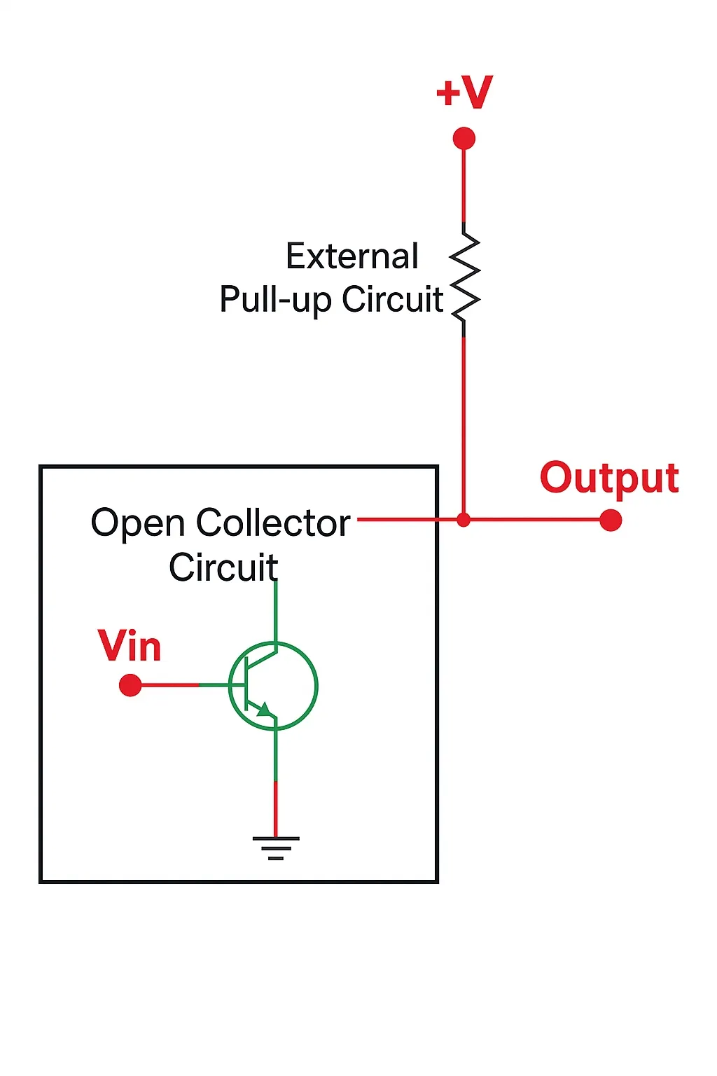
Open-collector is a common output type found in many integrated circuits. An open-collector output behaves like a switch that either connects to ground or is open. In such outputs the collector of an NPN transistor is used as the output; the emitter is internally connected to ground. The open-collector output allows current to be sunk to the common reference.
Open-collector outputs require an external supply to produce a valid output voltage. If no supply is connected, the output voltage will not change, so an external pull resistor is needed to define the output level when the transistor is off.
Depending on the transistor type (NPN or PNP), the circuit can provide either current-sinking or current-sourcing behavior:
- For NPN: when the transistor is ON, it sinks current to ground; when OFF, the output floats until pulled up to the positive supply by a pull-up resistor.
- For PNP: when the transistor is ON, it sources current to the supply; when OFF, the output floats until pulled down to ground by a pull-down resistor.
Open-Collector Logic Diagram
2. Open-Collector Transistor Circuits
NPN Open-Collector Output
When an NPN transistor operates in an open-collector configuration, it functions as a solid-state switch, switching between fully ON (saturation) and fully OFF (cutoff). With no base bias the transistor is off; with appropriate base bias it is fully on. In this mode it does not operate as a linear amplifier.
Switching between cutoff and saturation allows an open-collector output to drive external loads that may require higher voltages or currents than a common-emitter configuration can provide. The limits are the transistor's maximum voltage and current ratings.
An advantage of an open-collector output is that the collector can be pulled up to any suitable positive supply, including a separate supply rail for the load. For example, a microcontroller output can switch a +12 V lamp or relay via an open-collector transistor.
The drawback is that when used to drive logic inputs or gates, an external pull-up resistor is usually required because the NPN transistor can only pull the output low to ground when conducting, but cannot drive it high when off. The pull-up resistor, connected between the collector and supply voltage, returns the output to high when the transistor is off.
The pull-up resistor value depends on the required load current and typically ranges from a few hundred to a few thousand ohms. Thus, an NPN open-collector output is a current-sinking output.
Open-Collector Switching Circuit
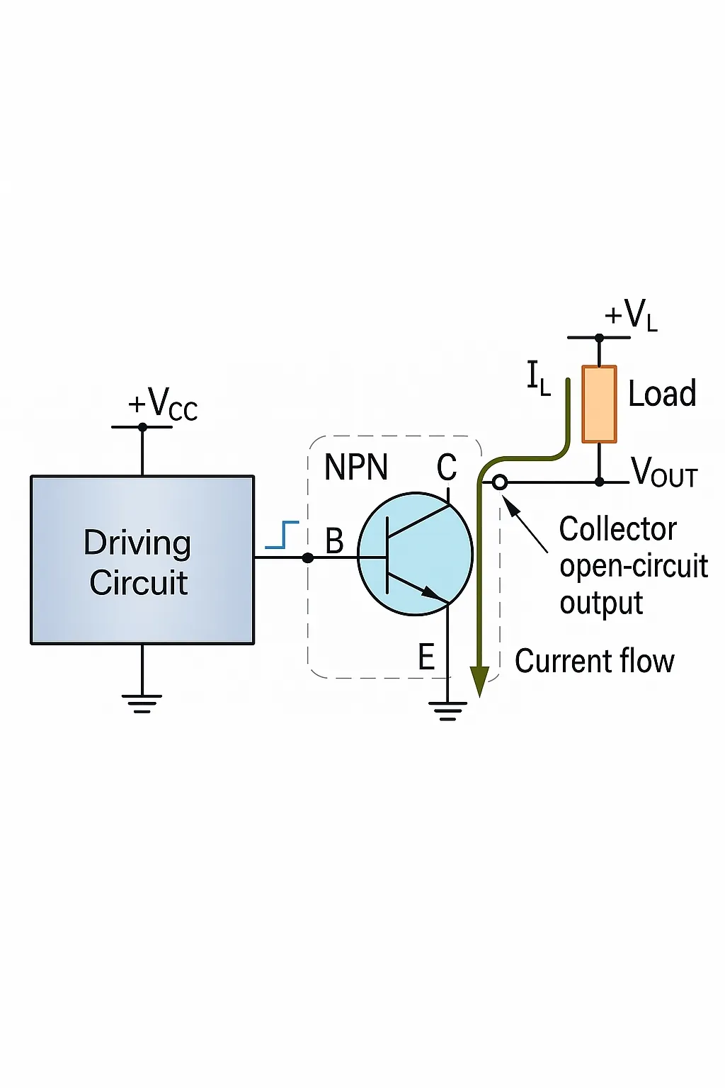
The diagram shows a typical open-collector switch arrangement for driving electromechanical devices or other switching applications. The NPN transistor base drive can come from any appropriate analog or digital circuit. The transistor collector connects to the load, and the emitter is tied to ground.
When a control signal is applied to the transistor base, the transistor conducts and pulls the collector and attached load down to ground, allowing load current IL to flow. The load current is given by Ohm's law:
Load current, I_L = load voltage / load resistance
When the base drive is removed, the NPN transistor turns off, the load is de-energized, and the output becomes open. The open-collector output thus functions as either open (OFF) or short to ground (ON).
An advantage is that the load need not share the same supply voltage as the driving transistor circuit; it can use a different higher or lower voltage, for example 12 V or 30 V DC.
Different transistors can be chosen to handle different currents and voltages, for example a small transistor for 10 mA at 6 V DC or a power transistor for several amperes at higher voltages. Open-collector Darlington arrangements are also possible.
Open-Collector Example No. 1
The example uses a +5 V digital output from an Arduino board to drive an electromechanical relay. If the relay coil is 12 V DC, 100 Ω, and the NPN transistor has a DC current gain (beta) of 50, calculate the base resistor needed to operate the relay coil.
The coil current is I = V / R.
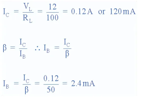
For a DC current gain of 50, the required base current is 2.4 mA, ignoring approximately 0.2 V VCE(sat). With VBE ≈ 0.7 V when the transistor is saturated, the base resistor RB is calculated as follows:
3. Open-Collector Operation
In open-collector logic, the output is either pulled to ground or left open. When pulled to ground, the output voltage is 0 V. When open, the output voltage is equal to the supply voltage via the pull-up resistor.
While NPN open-collector circuits provide current-sinking outputs, PNP transistors can be used in open-collector configurations to produce current-source outputs.
PNP Open-Collector Output
An NPN open-collector output actively pulls the load signal low when on and relies on a pull-up when off. Conversely, a PNP open-collector output can actively pull the output high to the supply rail when on, and requires an external pull-down resistor to bring the output low when off.
Thus, whether an open-collector configuration sinks current or sources current depends on the transistor type and the pull resistor used.
Open-drain MOSFETs and IGBTs can also be used in similar configurations. Unlike BJTs, enhancement-mode MOSFETs require an appropriate gate voltage rather than base current. The MOSFET source is tied to ground or the supply rail, and the drain is used as the open-drain output. The same pull-up or pull-down resistor conventions apply. The main differences are MOSFET channel power ratings and voltage protection requirements.
3. Open-Collector Circuits in TTL Gates
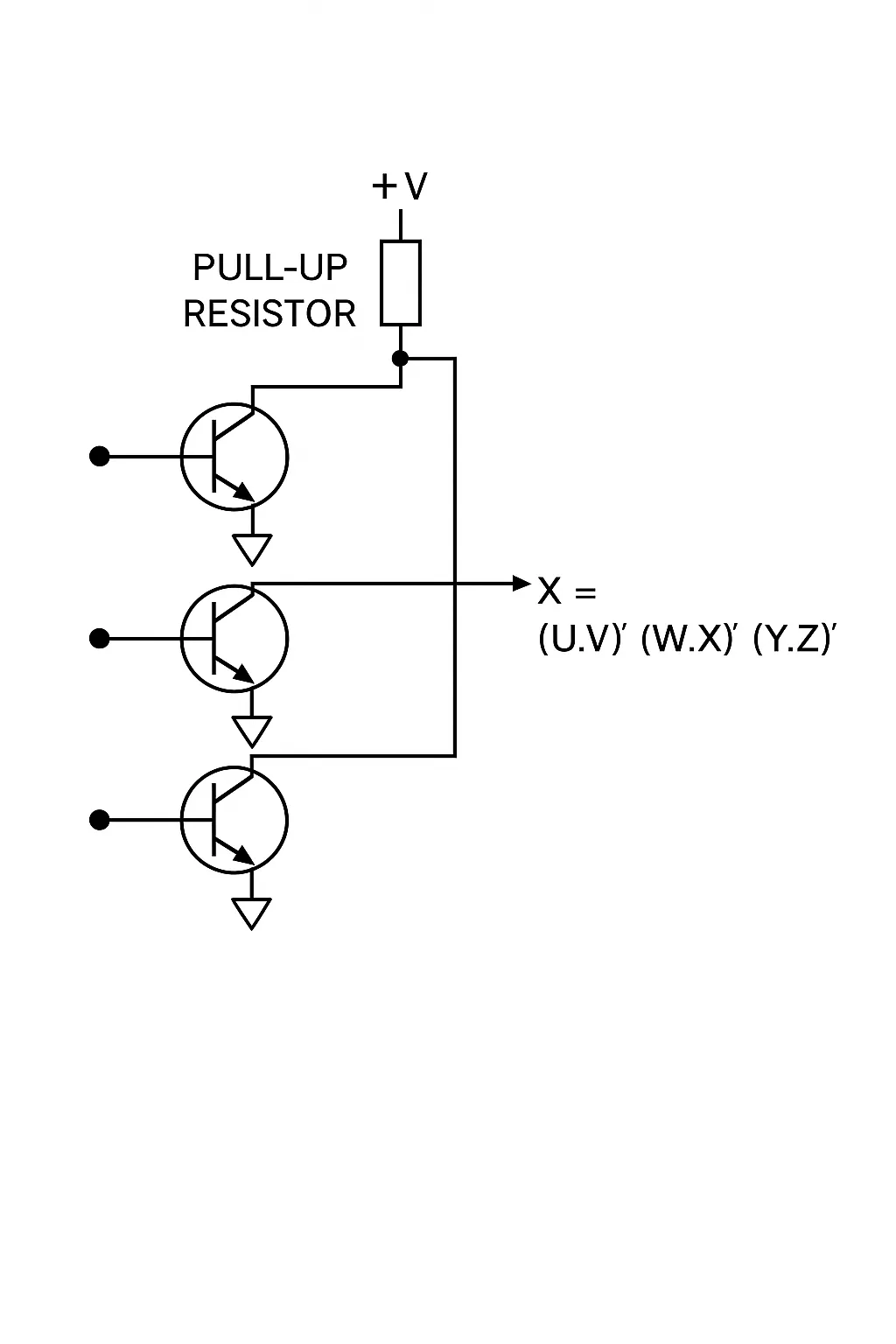
Removing a transistor from a totem-pole output in TTL can create open-collector TTL gates. By using pull-up resistors between outputs, a NAND gate can be converted to an AND gate.
Wired-AND and wired-OR functions can be implemented by connecting multiple open-collector outputs together on a common signal line. For example, multiple NAND outputs tied together with a pull-up perform an AND operation when all outputs are conducting.
4. Open-Collector Output Wiring
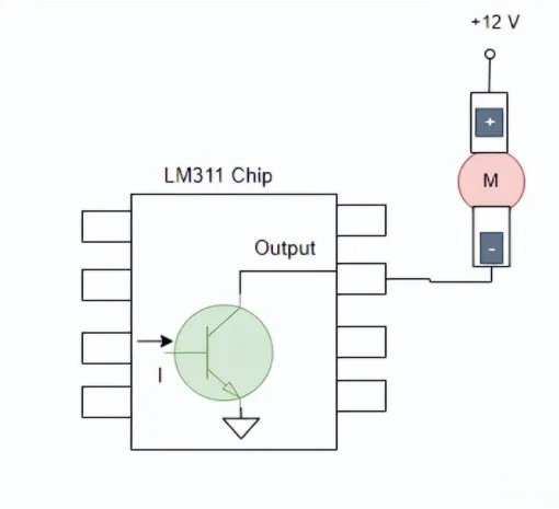
Open-collector outputs are often used in voltage comparators. Common comparator chips such as LM339, LM393, and LM311 use open-collector outputs.
When connecting a load to the output, the load should be connected to a positive voltage source that can drive the load. For example, if the load is a 12 V DC motor, the load should be connected to +12 V, and the motor negative terminal connected to the open-collector output so the comparator or driver can switch the motor ground.
Example: LM311 configured to drive a 12 V DC motor:
5. Purpose and Typical Uses
Open-collector logic means the output node can sink current but cannot source current. Open-collector outputs are useful when multiple devices need to share a common signal line.
Typical benefits include:
- Improved system flexibility for shared signals.
- Lower parasitic capacitance on the output node.
- Ability to connect larger loads to the collector without risking cross conduction within the driving device.
- Relative immunity to some electromagnetic interference, since there is no internal connection between output and supply when the transistor is off.
- Multiple open-collector outputs can be tied together to implement wired logic functions, such as wired-OR or wired-AND.
Because open-collector outputs are high impedance when not driven, they are useful as status indicators. A limitation is that open-collector outputs cannot source current, so they cannot drive multiple loads that require sourcing. The maximum voltage applied to a load is limited by the driving device's available VOH. For example, if the open-collector is driven by a 5 V device, the maximum pull-up voltage effectively available is 5 V.
6. Advantages and Disadvantages
Advantages
- Easy to wire together with other digital devices for shared signal lines.
- Less affected by crosstalk or noise in some designs because the off state is open.
- Open-collector outputs can sink substantial current, making them suitable for driving LEDs and other low-current devices.
- Useful in applications where electromagnetic interference considerations require no direct internal connection between output and supply.
Disadvantages
- Potential contention if two or more devices attempt to pull the line low simultaneously; careful design and layout are required to avoid conflicts.
- Open-collector outputs can only sink current, not source it. External pull-up resistors are required to obtain a high level.
- Slower switching can occur compared with some push-pull outputs because of the passive pull-up or pull-down network.