At many OEM new-model launches we often hear statements such as "the new model is built on the latest XXX pure-electric platform and offers XXX advantages." Typically, a brand develops a single EV platform for broad applicability and then derives multiple models from it.
Audi is different. Currently Audi uses four distinct electric platforms: the high-performance J1 platform shared with Porsche's Taycan; the MLBevo platform adapted from internal-combustion designs; the MEB platform shared with Volkswagen for badge-engineered models (for example, Audi's pure-electric Q4 is a rebadged Volkswagen ID.4); and the more advanced PPE platform, co-developed with Porsche, whose first models include the Q6 and the A6 Avant e-tron.
Overview of e-tron GT and Scope
The e-tron GT is based on the J1 platform and is the first Audi model equipped with an 800V high-voltage system, offering about 100 km of range from a 5-minute charge in ideal conditions. The following analysis focuses on the high-voltage system, network architecture, and ADAS.
01. High-voltage system
High-voltage systems refer to vehicle systems operating above 250 V. For the e-tron GT, the high-voltage architecture includes the high-voltage battery pack, the high-voltage booster (booster), the onboard charger, and related components.
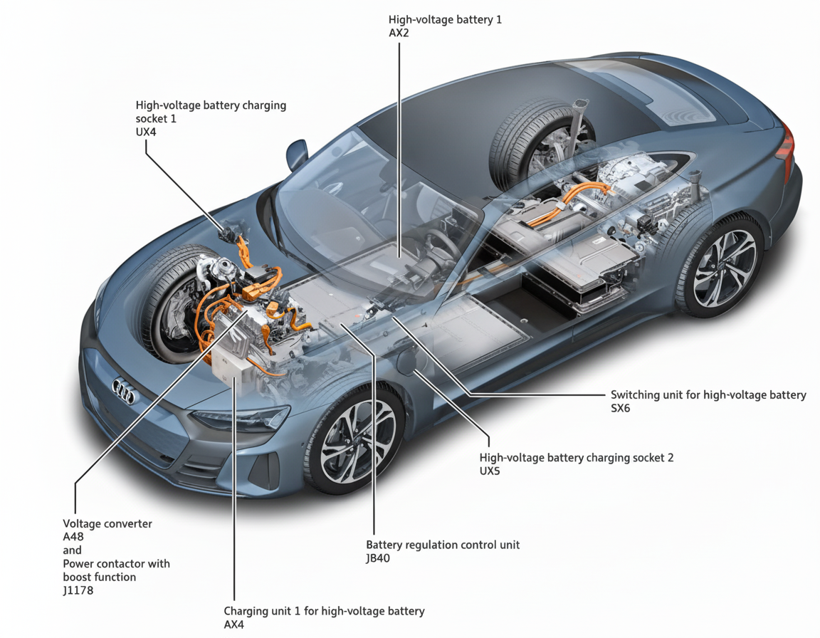
Figure 1 High-voltage system overview
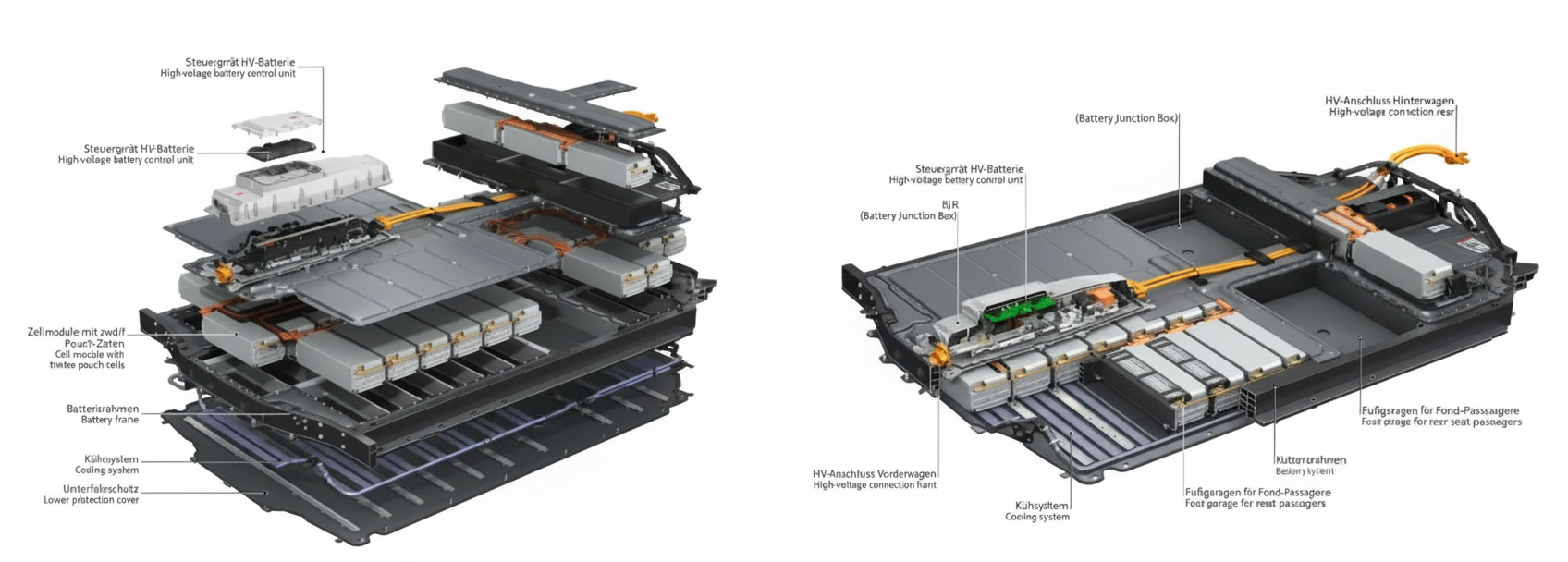
Figure 2 High-voltage battery exploded view
The traction battery is the core of the high-voltage system. Key specifications of the traction battery:
- 33 modules in total;
- cell arrangement per module: 162s2p;
- maximum charging power: 270 kW;
- battery pack weight: approximately 650 kg;
- nominal voltage: 726 V.
The battery modules are arranged in two layers. The left side in the diagram shows the lower-layer connections; positions 18, 19, and 20 correspond to upper-layer modules.
Each module integrates a module control unit that measures the voltages and temperatures of six cells and provides passive cell balancing up to 100 mA. Passive balancing dissipates excess charge as heat through resistors. Passive balancing activates when the battery management system detects a cell voltage deviation of 20% and the battery pack capacity is above 30%.
Module controllers are mounted transversely near the longitudinal beam, as shown in the diagram below.
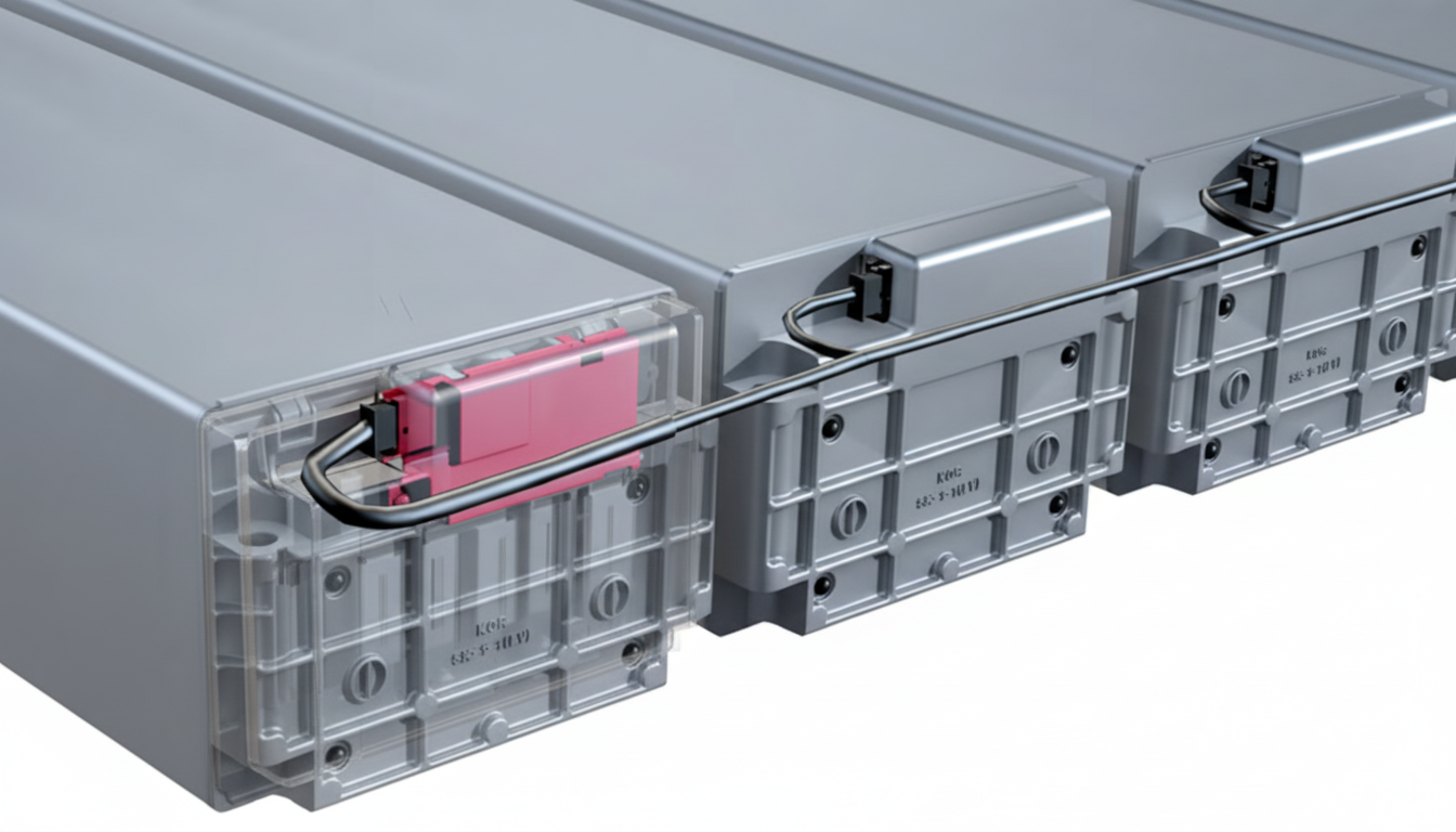
Figure 3 Module interconnection and controller mounting location
Each module contains 12 cells arranged as 6s2p. Each cell has a nominal voltage of 3.65 V and a capacity of 66 Ah, yielding a module voltage of 21.9 V.
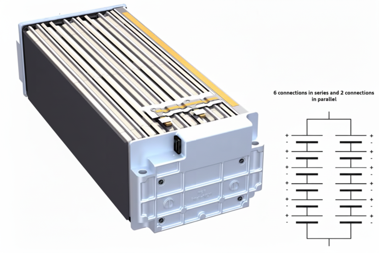
Figure 4 Module internal layout
High-voltage booster
The high-voltage booster is the vehicle's internal voltage conversion and energy distribution module.
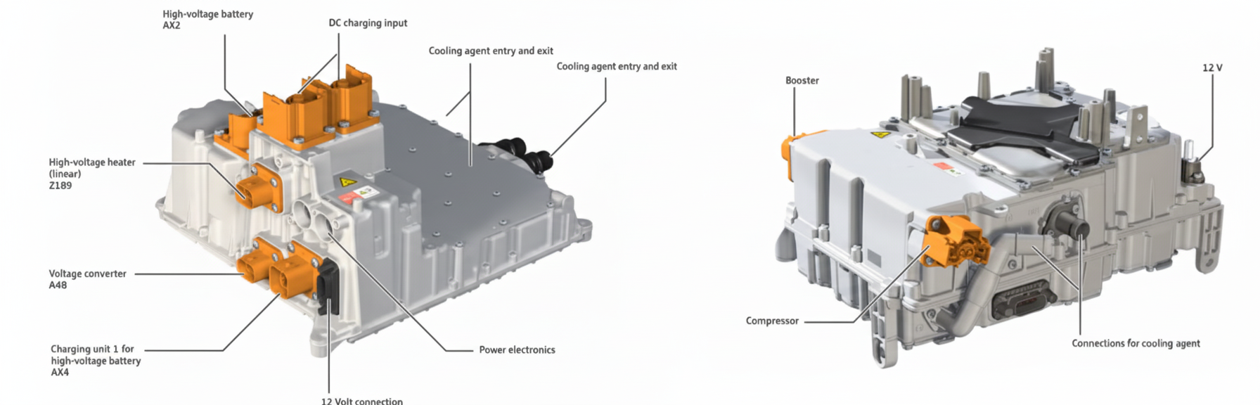
Figure 5 High-voltage booster
The booster provides three voltage conversion paths:
- 400 V to 800 V: Used when an external charging station supplies 400 V; the booster steps this to 800 V to charge the traction battery. The boost is implemented as a charge-pump topology that switches capacitors into series, as illustrated below.
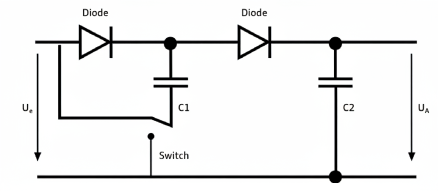
Figure 6 400 V to 800 V schematic
- 800 V to 400 V: Converts 800 V down to 400 V for high-voltage components that operate at 400 V, such as the air conditioning compressor and many electric drive components.
- 800 V to 12 V: Charges the low-voltage 12 V battery and supplies 12 V electrical systems. This path is active both during vehicle operation and, if necessary, when the vehicle is parked for extended periods. When the system detects that the 12 V battery voltage is low and the traction battery has sufficient state of charge, the high-voltage booster will automatically charge the 12 V battery.
Overall, the high-voltage design is conservative: only the charging chain is 800 V-capable, while other high-voltage components remain at 400 V. This contrasts with the Hyundai IONIQ 5, where the high-voltage architecture is largely all-800 V.
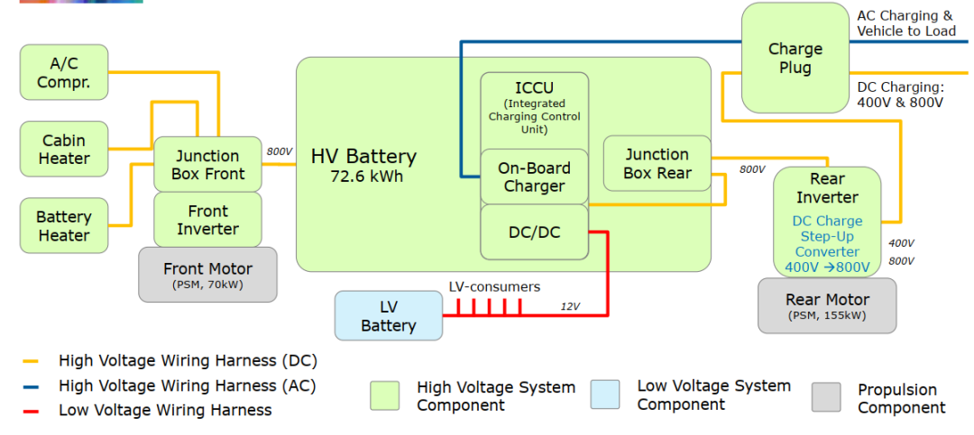
Figure 7 Hyundai IONIQ 5 high-voltage system
02. Low-voltage 12V battery
The e-tron GT is Audi's first model to use an 800 V charging system and also the first Audi to adopt a lithium iron phosphate (LiFePO4) 12 V battery instead of a traditional lead-acid battery. Compared with lead-acid batteries, the lithium 12 V battery offers:
- approximately 50% weight reduction for equivalent capacity;
- about 2.5 times longer lifespan and 7 times better cycle stability;
- improved voltage stability;
- approximately 20% smaller volume compared with lead-acid alternatives.
The 12 V battery contains eight cells arranged as 4s2p. Each cell has a nominal voltage of 3.3 V, giving a pack nominal voltage of 13.2 V. The battery control unit is mounted on the battery housing top, with control and power circuits separated. Tesla's design integrates the control board internally and combines control and power into a single connector, indicating a higher level of integration compared with the e-tron GT.
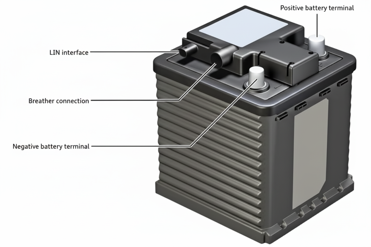
Figure 8 e-tron GT 12 V battery
12 V battery operating strategy across voltage levels:
- If voltage is greater than 15.5 V and remains so for 120 s, charging is inhibited until the voltage drops below 15.5 V;
- If voltage is below 10 V, the battery will not supply external loads until the charging path is opened;
- If battery voltage drops below 8 V, the battery is considered defective and requires replacement.
The 12 V charging path: the traction battery at 800 V is stepped down by the high-voltage booster to 12 V to charge the 12 V battery.
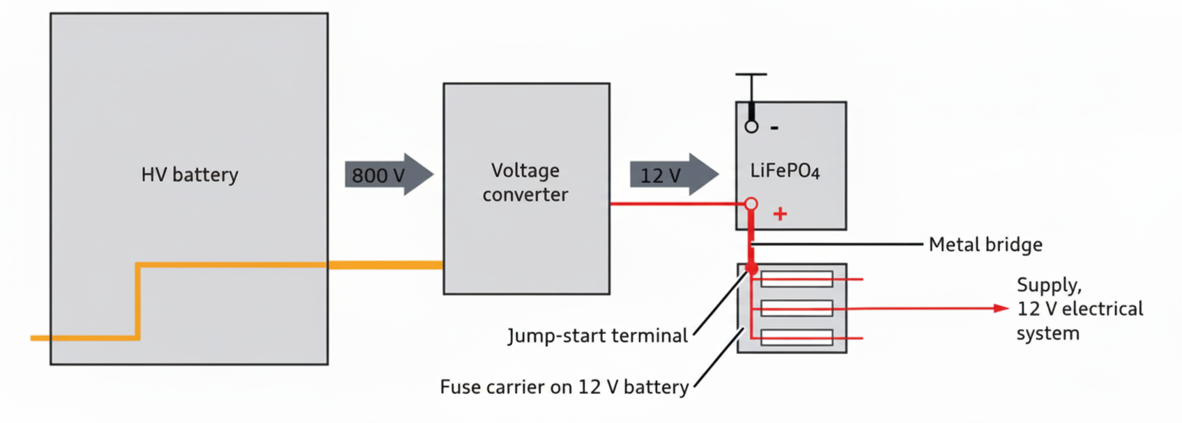
Figure 9 12 V battery charging path
When the vehicle is stationary, if the 12 V battery capacity falls below a defined threshold and the traction battery state of charge (SOC) is above 10%, the traction battery will be used to recharge the 12 V battery. The logic is:
- If the 12 V battery capacity is less than 8 Ah and the traction battery SOC is greater than 10%, the charging path is activated;
- Charging stops when the 12 V battery reaches 20 Ah or after 30 minutes of charging;
- During prolonged parking, this automatic charging path can be activated up to 8 times.
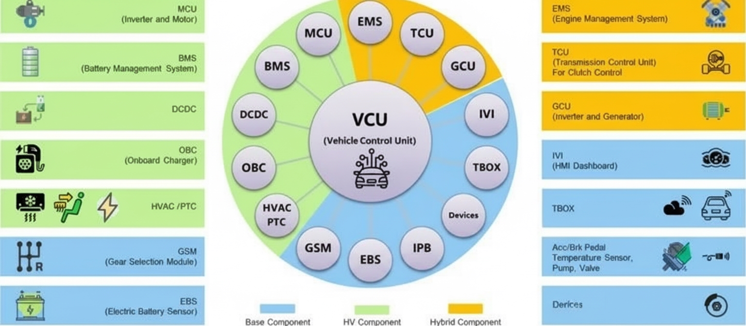
03. Network architecture
The network architecture forms the vehicle's electrical backbone for controller communication. The e-tron GT network consists of several local networks, including the Comfort CAN, Comfort CAN2, and Extended CAN networks.
Comfort CAN
This network handles doors, trunk, anti-theft, seats, and related functions and is primarily a 500 kbps CAN bus.
Key controllers on this network include:
- J136: seat control unit, linked to the steering column;
- J223: electric spoiler control unit;
- J386: door control unit;
- J926: rear door control unit;
- J387: front passenger door control unit;
- J393: convenience control unit;
- G578: anti-theft sensor;
- H12: horn;
- J938: rear trunk motor control unit;
- J521: front passenger control unit;
- J533: data bus diagnostic unit;
- J453: steering wheel control unit;
- J605: rear trunk control unit.
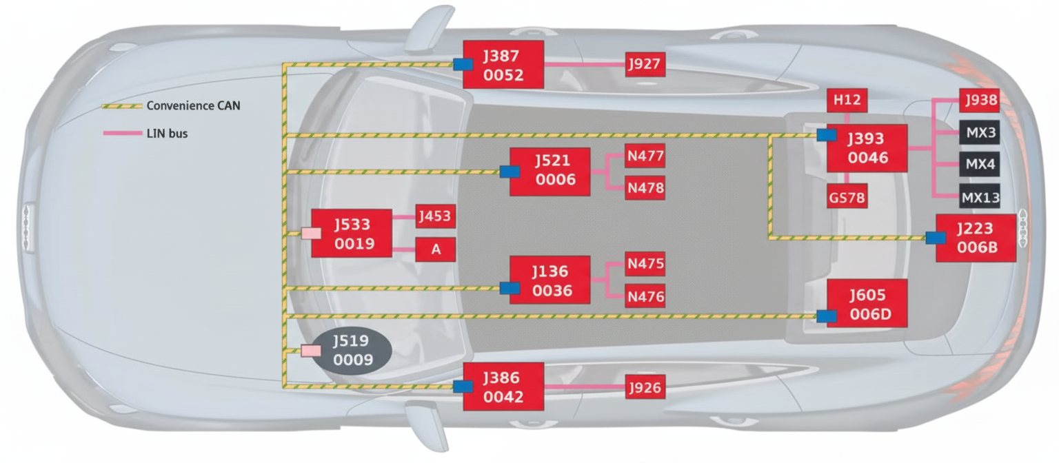
Figure 10 Comfort CAN network
Comfort CAN2
Comfort CAN2 controls vehicle accessories such as mirrors, headlights, wipers, and seat ventilation. It uses mainly LIN buses.
Key nodes include:
- J519: onboard power supply control unit;
- EX5: exterior mirror;
- G397: rain and light sensor;
- J866: electrically adjustable steering column control unit;
- MX1/MX2: left and right headlights;
- J979: heater and air conditioning controller.
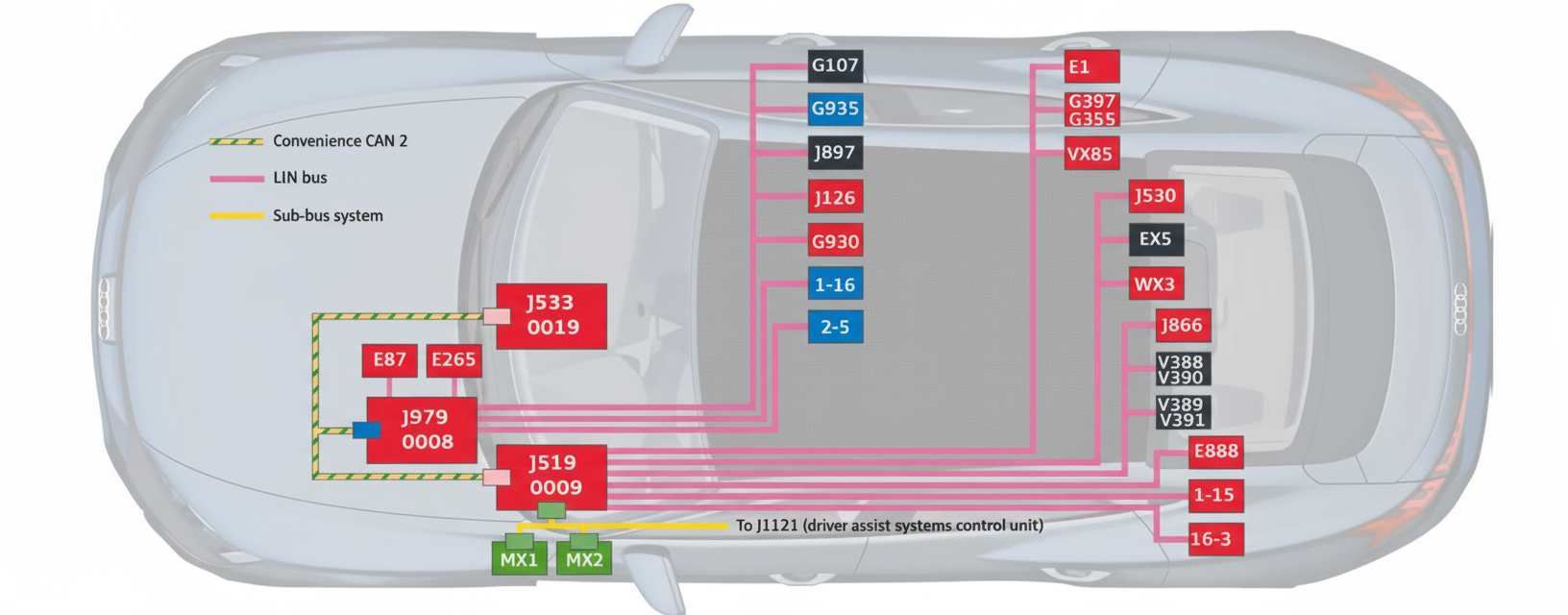
Figure 11 Comfort CAN2 network
Extended CAN
The Extended CAN network connects the tire pressure monitoring unit J502, lane-change assist units J769/J770, reverse camera control unit J772, night-vision control unit J853, and simulated engine sound control units J1167/J1177.
FlexRay network
FlexRay is used primarily for chassis-by-wire functions due to its safety and reliability properties. In China, chassis-by-wire implementations are still commonly based on CAN. The FlexRay topology for the e-tron GT includes:
- J104: electronic stability control (part of ADAS braking control);
- J234: airbag control unit;
- J500: EPS electric power steering;
- J527: steering column control unit;
- J539: Bosch iBooster;
- J1121: ADAS control unit;
- J1019: rear-wheel steering control;
- J1234/J1235: front and rear axle electric drives;
- J428: adaptive cruise ECU connected to the main radar;
- J1088/J1089: front-left and front-right radars;
- J769/J770: lane-change assist units and rear-left radar.
Diagnostic CAN / Ethernet
This network connects the OBD port for diagnostic readout of faults and configuration parameters and for controller software updates. Because some controller software images are large, many vehicles now include an Ethernet-based diagnostic path.
Nodes include J533 as the gateway, J794 as the infotainment unit, and J949 as the e-call unit. J898 represents the AR HUD connection.
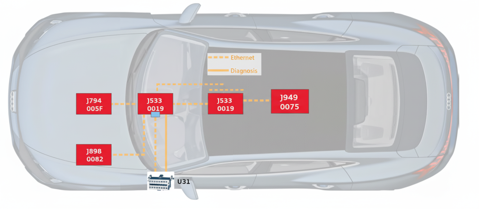
Figure 12 Diagnostic CAN / Ethernet network
Overall, the network architecture is conventional and does not follow the central domain controller architecture used in Audi's sibling ID-series from Volkswagen; it is a straightforward, modular approach.
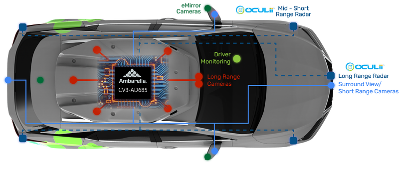
04. ADAS system
Functionally, the e-tron GT's ADAS is a standard Level 2 driver assistance suite consistent with Audi models from 2017 onwards (A6/A7/A8/Q7/Q8), including adaptive cruise, parking assist, and urban assist. The system architecture is shown below for reference.
Components include 12 ultrasonic sensors (G203–G206, G252–G255, G568–G717), the ADAS control unit J1121, four 360-degree cameras R243–R246, the center infotainment display J685, ESC J104, and infotainment unit J794.
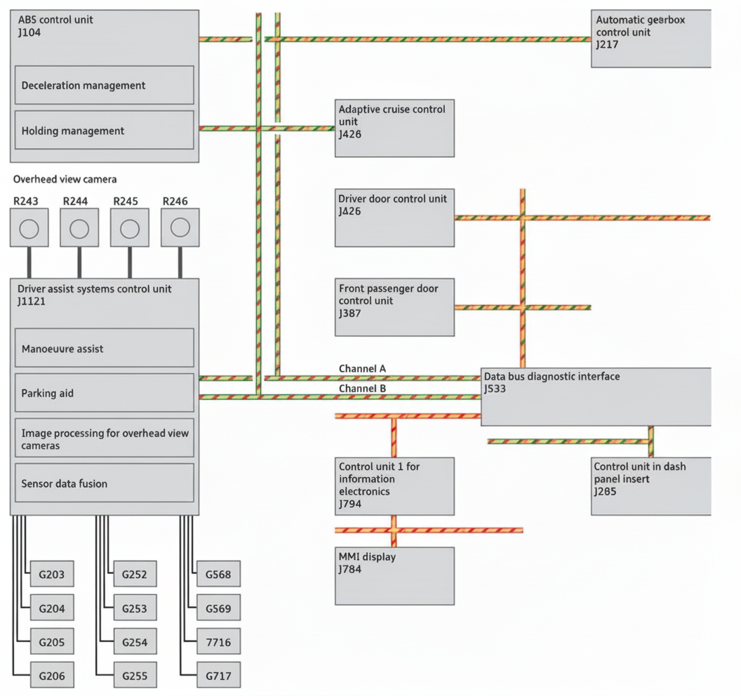
Figure 13 ADAS system architecture
05. Conclusion
Under rapid technological iteration, the e-tron GT's engineering is competent but generally conservative. The vehicle combines new elements, such as an 800 V charging path and a lithium 12 V battery, with many existing 400 V components and a conventional distributed network architecture. Compared with newer, more aggressively integrated EV designs from some manufacturers, the e-tron GT reflects a more cautious, incremental engineering approach rather than a radical systems overhaul.