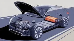
Electric vehicle drive motors, including permanent magnet synchronous motors (PMSM), induction motors, and emerging rare-earth-free designs, depend on sophisticated power electronics and control systems. The printed circuit board (PCB) serving as the motor inverter and controller is the critical link that converts battery DC power into precisely modulated AC waveforms while managing high currents, fast switching, and real-time feedback. At Aivon, we specialize in high-reliability PCBs for EV traction inverters, in-wheel motors, and multi-gear electric drive systems, delivering superior power integrity, thermal performance, and functional safety.
Motor Operating Principles and Inverter PCB Requirements
EV drive motors operate through electromagnetic interaction between stator windings and rotor magnetic fields. Precise control of phase currents and voltages is essential for torque, efficiency, and speed regulation.
This demands advanced inverter PCBs featuring:
- High-Current Power Stages: Heavy copper layers (3oz-6oz or busbar-integrated) with optimized trace geometry to minimize resistive losses and I2R heating in SiC or IGBT-based inverters.
- High-Speed Gate Drivers: Tight impedance control and minimal loop inductance for fast switching (especially in 800V platforms), requiring careful layout to reduce overshoot and EMI.
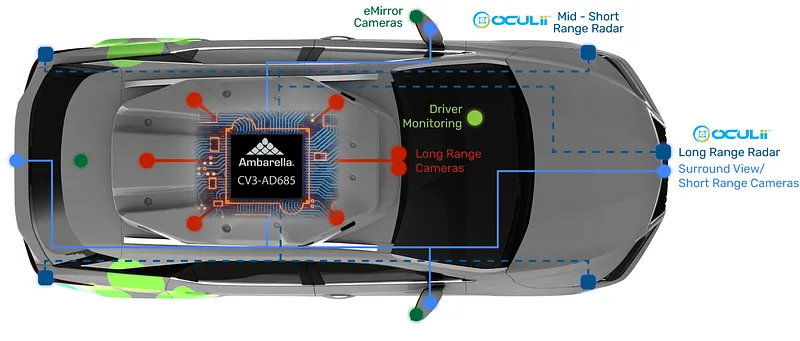
- Current and Position Sensing: Low-noise analog front-ends for shunt or Hall-effect current sensors and resolvers, with excellent isolation from high-voltage power planes to maintain signal accuracy.
Tesla's 3D6 motor rotor design and similar high-performance motors further increase demands on dynamic current control, pushing PCBs toward higher switching frequencies and more sophisticated thermal solutions.
In-Wheel Motor Systems and Distributed Control Architectures
In-wheel motors eliminate traditional drivetrains by placing motors directly at each wheel, offering superior torque vectoring and packaging efficiency. However, they create unique PCB challenges due to space constraints, vibration, and thermal cycling.
PCB design adaptations include:
- Compact, Rugged Layouts: HDI PCBs with microvias to integrate power stages, gate drivers, and MCUs in limited wheel-end space.
- Vibration-Resistant Construction: Enhanced via filling, thicker copper, and high-Tg materials to withstand continuous mechanical stress.
- Decentralized Power Management: Independent inverters per wheel require robust isolation, redundant protection circuits, and reliable communication interfaces (Ethernet or CAN) with controlled impedance routing.
These systems intensify the need for excellent thermal dissipation, as motors and controllers share confined, high-temperature environments.
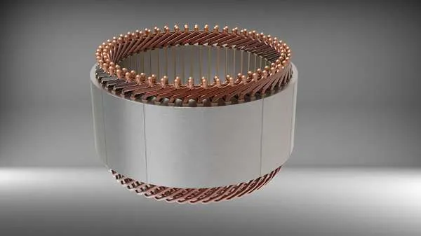
Multi-Gear and Flat-Wire (Hairpin) Motor Integration
Multi-gear electric drive systems and flat-wire (hairpin) stator windings improve efficiency across wide speed ranges but introduce new control complexities.
PCB implications include:
- Dynamic Switching Control: More frequent gear shifts and variable winding configurations require faster processing and cleaner signal integrity for real-time torque coordination.
- Higher Current Handling: Flat-wire motors often support higher power density, demanding thicker copper and optimized thermal vias to manage increased phase currents.
- Application Barriers: Challenges such as manufacturing complexity, acoustic noise, and thermal hotspots in flat-wire designs translate to stricter PCB requirements for current sensing accuracy and EMI suppression.
BYD and other manufacturers' integrated high-voltage powertrains highlight the need for tightly coupled motor controller PCBs that combine power and control functions with minimal parasitic inductance.
Rare-Earth-Free Motors and Emerging Rotor Technologies
The push toward rare-earth-free motors (using ferrite, reluctance, or wound-rotor designs) reduces supply chain risks but often requires more sophisticated control algorithms to match the performance of permanent magnet motors.
PCB-level support includes:
- Advanced Control Algorithms: Higher computational demands on the MCU or SoC, necessitating cleaner power delivery and faster memory interfaces.
- Sensor Fusion: More extensive rotor position and temperature sensing networks, requiring low-noise analog routing and precise synchronization.
- Wider Operating Ranges: Expanded speed and torque demands place greater stress on inverter switching elements and thermal management systems.
Thermal Management and High-Voltage Design Considerations
High-power motor controllers generate significant heat, especially in 800V architectures with rapid acceleration and regenerative braking.
Effective PCB solutions feature:
- Advanced Thermal Paths: Copper coins, heavy copper planes, and metal-core substrates to transfer heat away from power devices.
- High-Voltage Isolation: Increased creepage distances, reinforced dielectrics, and physical barriers between HV and LV sections.
- Power Integrity: Multi-domain PDNs with extensive decoupling to support fast current transients without voltage instability.
These elements are critical for preventing thermal runaway, maintaining efficiency, and ensuring compliance with automotive safety standards (ASIL).
Manufacturing and Reliability for EV Motor Control PCBs
Producing motor controller PCBs for automotive use requires:
- Automotive-grade materials with stable electrical and mechanical properties across extreme temperatures.
- Precision processes for heavy copper etching, via filling, and lamination to ensure consistent performance.
- Comprehensive validation including thermal cycling, vibration testing, partial discharge analysis, and functional safety verification.
Common failure mechanisms such as via cracking, solder fatigue under vibration, and dielectric breakdown under high voltage must be addressed through robust design and process control.
The performance, efficiency, and safety of electric vehicle drive motors ultimately depend on the quality of their controlling PCBs. From high-current inverter stages and sensor interfaces to thermal management and functional safety features, every aspect of motor system design is enabled by advanced PCB engineering.
Aivon provides specialized high-power PCB solutions for EV traction motors, in-wheel systems, and integrated powertrains. Our expertise in heavy copper design, high-voltage isolation, signal integrity, and automotive reliability helps manufacturers overcome the complex challenges of modern electric drive systems while accelerating development of more efficient and capable vehicles.