Introduction
As automotive technology evolves, the introduction of FPGAs (field-programmable gate arrays) has changed how hardware is deployed in vehicles. FPGAs provide flexibility and performance that enable a range of automotive applications.
With the growth of electric and new-energy vehicles, vehicle intelligence is a major trend. FPGAs are used across engine control units, driver assistance, and communication systems, including vehicle-to-vehicle (V2V) and vehicle-to-infrastructure (V2I) communication. V2V and V2I enable real-time sharing of traffic information, improving safety and efficiency. The following sections describe FPGA applications in engine control units and driver assistance systems.
Engine Control Unit (ECU)
Engine control has become an important lever for improving fuel economy. Implementing an ECU on an FPGA offers a significant advantage because the logic can be reconfigured as needed.
Engine control algorithms include ignition timing, fuel injection quantity, and valve timing. Using FPGAs, manufacturers can optimize control algorithms for different engine types and driving conditions to improve efficiency and performance.
A cyclical method for controlling an internal combustion engine includes: maintaining training data of a mapping function that identifies the engine; filling a buffer with adaptive data for a given cylinder, where adaptive data are the mapping function inputs and outputs captured over multiple operating cycles for that cylinder; combining the mapping function training data with the adaptive data; identifying the mapping function from the combined dataset using weighted least squares; predicting the combustion characteristics for the given cylinder in the next cycle using the mapping function and current-cycle input measurements; and using one or more actuators to control the engine in the next cycle based on the predicted combustion characteristics for that cylinder.
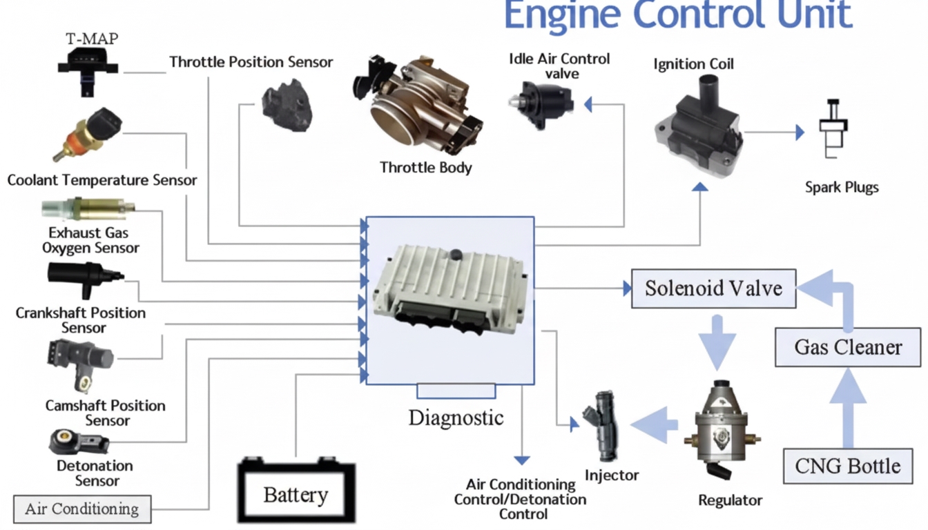
Traditional Engine Control Parameters and Components
The following parameters and components contribute to improved engine control:
- Injection duration
- Injection timing
- Fuel injection pressure
- Low-pressure fuel pump
- Ignition timing
- DBW valve
- Tumble valves
- Short/long intake runner valves
Typical ECU I/O used to run the management system include:
- 12 injector outputs, usable as auxiliary outputs
- 8 ignition outputs
- 8 auxiliary outputs, capable of driving high or low level
- 8 digital inputs with configurable internal pull-up/pull-down resistors
- 5 trigger inputs, configurable as magnetic reluctor or digital I/O
- 4 VSS or turbine speed inputs, configurable as magnetic reluctor or digital I/O
- 16 general analog inputs, of which 4 can be configured for temperature sensing and 2 for oxygen sensors
At idle, an engine may run near 14.7:1 air-fuel ratio. Under light load, the ratio can be leaned further without misfiring; how lean depends on factors such as drivetrain and combustion efficiency. Ratios around 16:1 are typically acceptable, and in some vehicles light-load ratios can reach 20:1. A control strategy can adjust the overall mixture ratio from a lean 16.5:1 to a richer 12.5:1 according to load and speed conditions. Intelligent control dynamically adjusts these parameters.
Machine learning provides an effective way to capture complex cyclic combustion patterns while avoiding explicit modeling of the underlying mixture state and composition, assuming an appropriate abstract mapping function is chosen. A key limitation is that machine learning is data-driven and often requires substantial data to cover large-dimensional spaces adequately.
An open-source ECU project can be used to study these concepts and related theory.
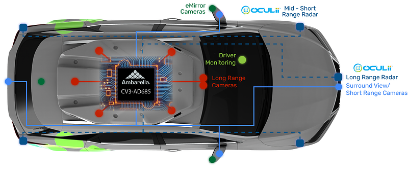
Driver Assistance Systems
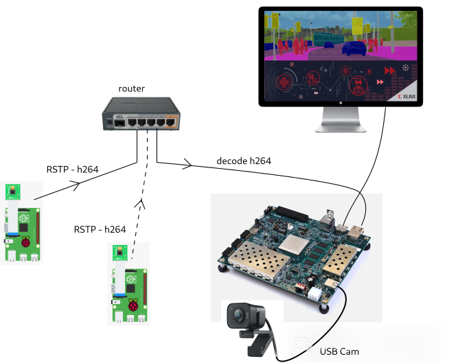
FPGAs play a key role in advanced driver assistance features such as lane-keeping assistance, adaptive cruise control, and automatic emergency braking. By processing real-time video and sensor data on FPGA hardware, vehicles can identify lane markers and obstacles and adjust speed and steering to maintain safe distances.
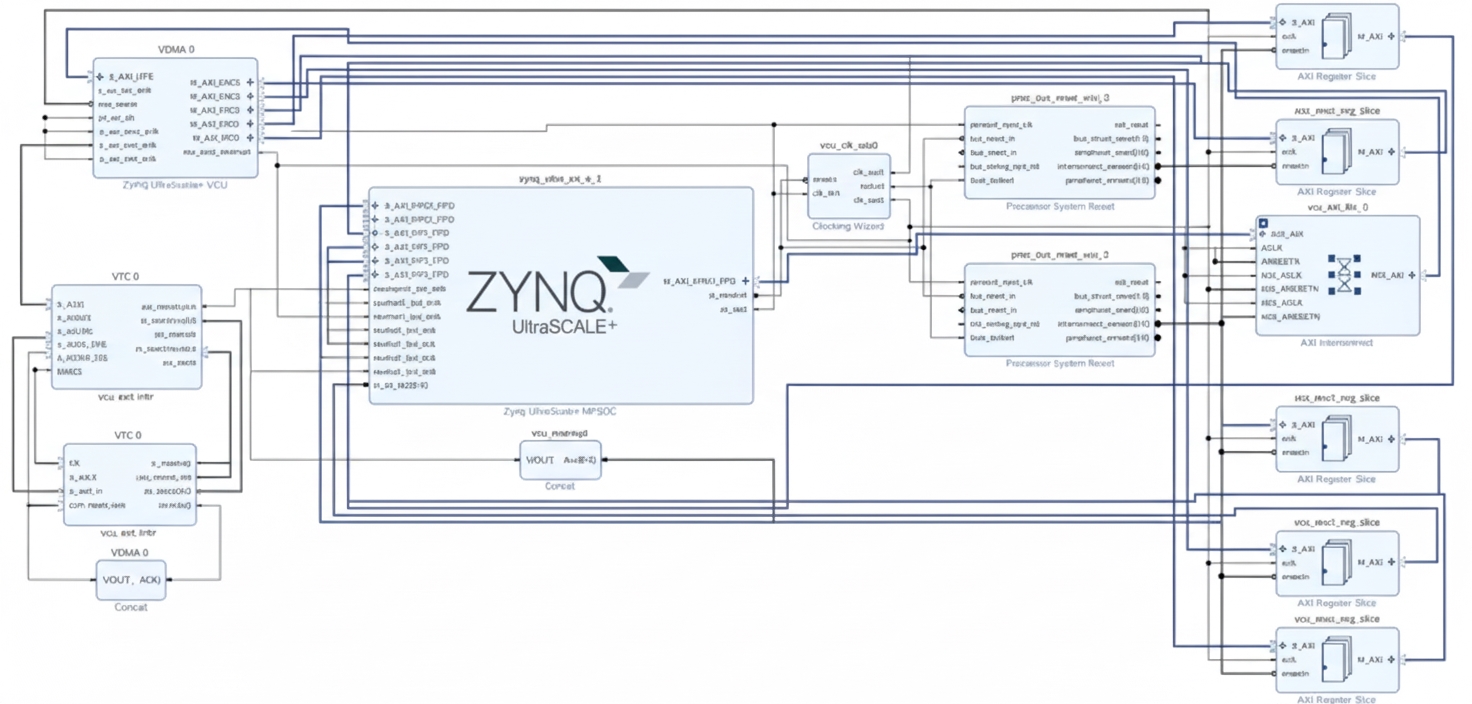
ASIC development in this domain has advanced rapidly, and companies such as NVIDIA and HiSilicon produce dedicated ASICs for perception and inference. While FPGAs offered advantages during early exploration, ASICs are increasingly dominant for production systems. The following image shows a complete FPGA-based assistance system architecture.
Conclusion
FPGAs provide performance, flexibility, and functionality that benefit automotive development. Features such as partial reconfiguration can enable integration of non-concurrent functions and novel hardware-level fault tolerance mechanisms. However, FPGA use in production ADAS and control systems remains largely exploratory, and ASICs are expected to take the lead in many production applications.