Overview
As new-energy vehicle technology evolves, and to align with national policies promoting adoption of green new-energy vehicles, vehicle manufacturers have launched a range of electrified models including battery electric, hybrid, and hydrogen fuel cell vehicles. Electrification is progressively replacing conventional fuels as a vehicle propulsion source. High-voltage wiring harnesses form the primary connection and power-transmission system for vehicle propulsion and functions. Because these systems operate at voltages above human-safe levels, harness design and routing present specific technical challenges.
1. High-voltage wiring design
1.1 Dual-rail harness architecture
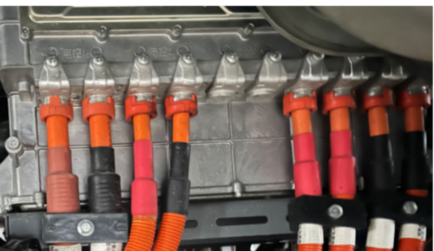
High-voltage wiring harnesses generally use a dual-rail architecture. Since traction batteries provide high DC voltages that exceed safe touch voltages, the vehicle body cannot be used as a chassis ground for the high-voltage system. DC high-voltage circuits must follow a strict dual-rail design. Common high-voltage harnesses include those for the drive system, traction battery, charging inlet, air-conditioning compressor, and power steering pump.
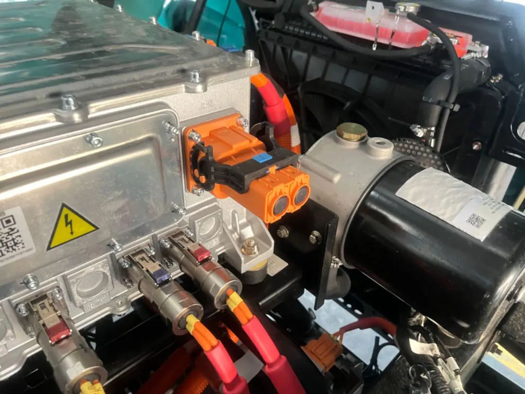
1.2 High-voltage connector selection
High-voltage connectors are responsible for high-voltage, high-current connections and are critical for occupant safety. Selection criteria include high-voltage withstand, ingress protection rating, circuit interlock features, and shielding. Suppliers with mature, proven products are typically preferred.
1.3 Shielding design
Because high-voltage circuits can generate significant electromagnetic interference (EMI), shielded conductors with braided shielding are commonly used. Connectors with integrated shielding are selected where possible so that crimping can form a continuous connection between connector and cable shielding, reducing EMI from the harness.
2. Harness routing and layout
2.1 Layout principles
Proximity principle: Route high-voltage harnesses along the shortest practical paths to minimize voltage drop and reduce weight and cost.
Safety and serviceability: Routing must also satisfy concealment, crash-safety regulations, and service access. Proper protection is required to prevent electric shock, fire, or other hazards resulting from improper routing.
2.2 Common routing strategies
Two common approaches separate high-voltage and low-voltage wiring to reduce EMI coupling: layered routing and parallel routing.
Layered routing
Layered routing separates high-voltage and low-voltage harnesses by distance or by mounting on different planes to avoid interference with low-voltage control units and signal transmission. Illustrations show typical layered arrangements.
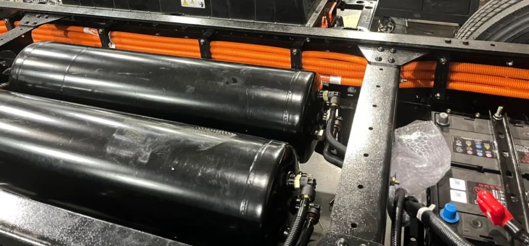
Parallel routing
Parallel routing runs harnesses in the same general direction but mounted on different sides of the frame or body, ensuring the high- and low-voltage bundles run in parallel without crossing. An example shows high-voltage harnesses on the left side of the frame and low-voltage harnesses on the right.
Depending on vehicle structure, component layout, and available space, engineers often combine both methods to minimize or eliminate high-to-low voltage interference.
2.3 Safety-focused routing guidelines
Beyond separation strategies, routing must prioritize safety and maintainability.
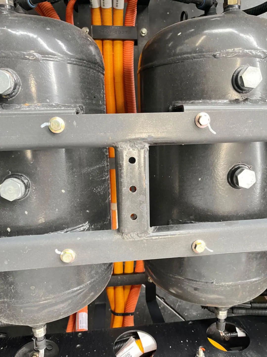
Avoid vibration sources
Route and secure high-voltage harnesses away from strong vibration sources, such as compressors and pumps, and ensure harnesses do not experience relative motion with the connected high-voltage components. If avoidance is not feasible, leave sufficient service slack based on vibration amplitude and motion envelopes so the harness is not subjected to tensile stress.
On rough roads, mounting points can shift or detach, momentarily increasing distance between supports and stressing the harness. Harness lengths should be balanced to provide slack for movement while avoiding excess length that causes twisting.
Avoid high-temperature zones
Keep harnesses away from high-temperature components to prevent insulation melting or accelerated aging that could expose conductors and cause shorts. Common heat sources include compressors, brake lines, power steering pumps, and hot fluid lines.
Maintain minimum bend radius
Respect minimum bend radii during installation. Excessive bending increases conductor resistance at bends, raising voltage drop and potentially increasing local heating. Long-term overbending can age and crack insulation. As a guideline, the minimum inner bend radius of a high-voltage conductor should generally not be less than four times the conductor outer diameter.
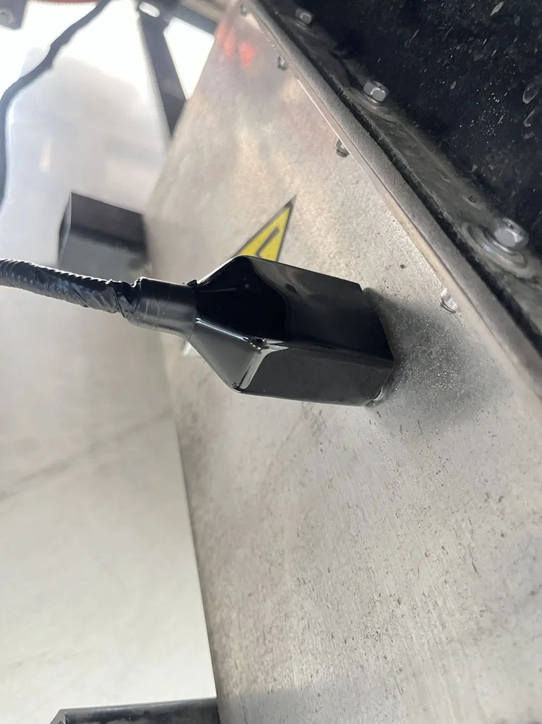
Example: correct routing at a connector (left) vs incorrect routing (right).
Avoid excessive bending at connector tails. Connector exit conductors should be straight for a short distance; do not torque or bend conductors close to the connector, and avoid applying rotational loads.
2.4 Sealing and waterproofing
Sealing measures such as cable grommets, heat-shrink with adhesive, and rubber seals are used between mating connectors and at cable exits to achieve IP67-level ingress protection.
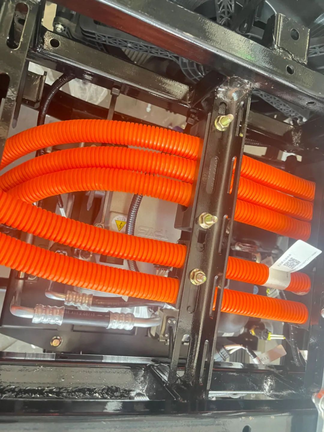
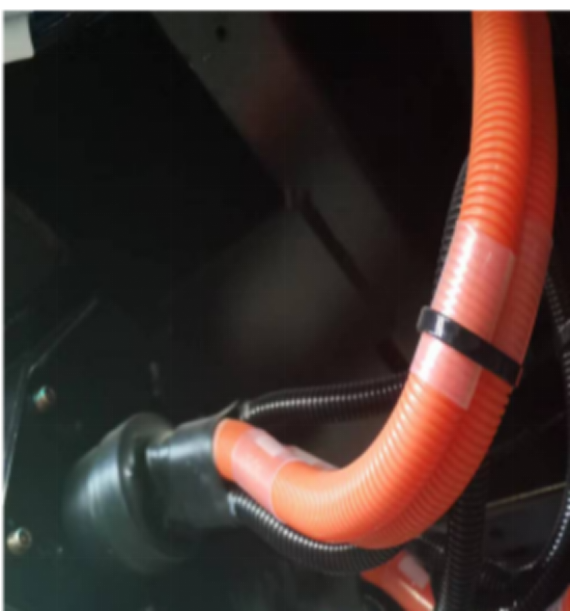
Common protective coverings are applied to harnesses for abrasion resistance, noise reduction, thermal shielding, and aesthetics. Typical materials include orange high-temperature, flame-retardant corrugated tubing or orange high-temperature, flame-retardant fabric sleeves that fully cover the harness.
3. Sealing methods
Various sealing methods are applied between high-voltage conductors and high-voltage connectors, including wire seals, adhesive-lined heat-shrink tubing, and rubber components, to meet IP67 dust and water protection requirements.
Adhesive-lined heat-shrink sealing (left) and connector blind-plug sealing (right).
Connector tail with adhesive sleeve sealing (left) and U-shaped harness routing to prevent issues (right).
4. YIWEI Automotive new-energy vehicle harness capabilities
YIWEI Automotive has established an in-house new-energy wiring harness production line capable of the full manufacturing flow from engineering drawings through component feeding, stripping, crimping, kitting, assembly, and final testing. This production line supports manufacture of harnesses for the company's own vehicles and for external customers with various requirements.
4.1 High-voltage harnesses
High-voltage harnesses are the primary power-transmission conduits for electrified vehicles and have stricter material and technical requirements than conventional wiring. To meet vehicle functional requirements, YIWEI Automotive procures shielded high-voltage cables in a range of cross-sections, from 2.5 mm2 to 70 mm2.
4.2 Dedicated production equipment
Manufacture of high-voltage harnesses follows strict processes. To ensure quality and meet production requirements, the company has invested in dedicated equipment including pneumatic unspooling machines, wire stripping machines, terminal pull-test machines, and insulation testing instruments.
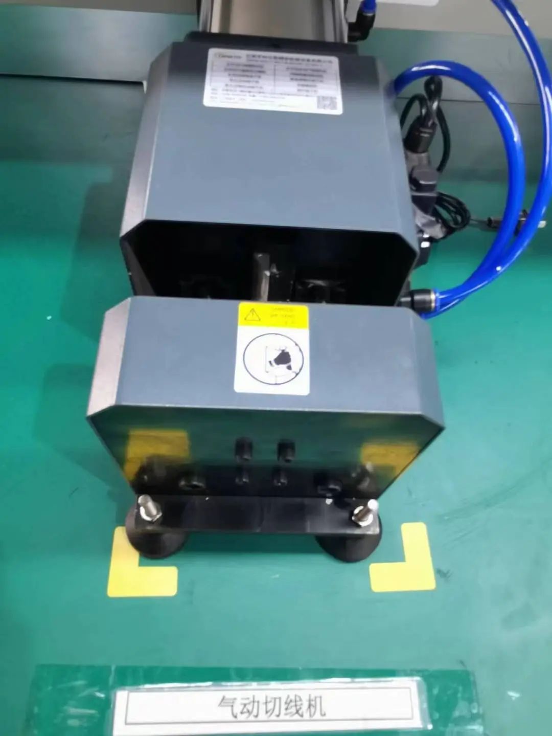
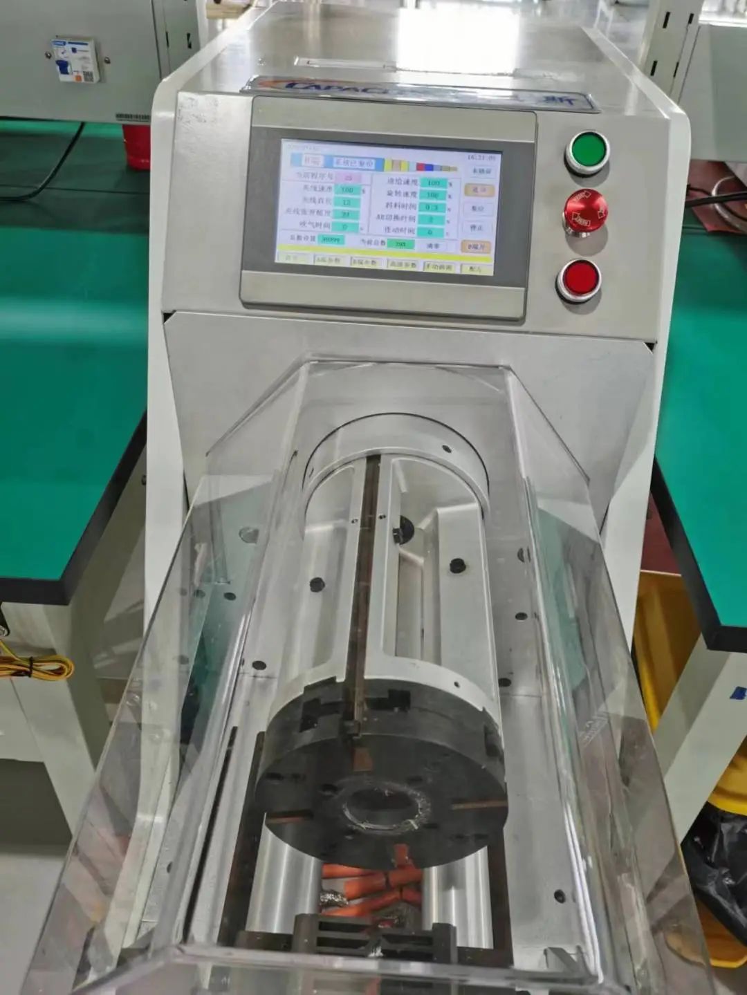
Pneumatic unspooling machine (left) and wire stripper (right).
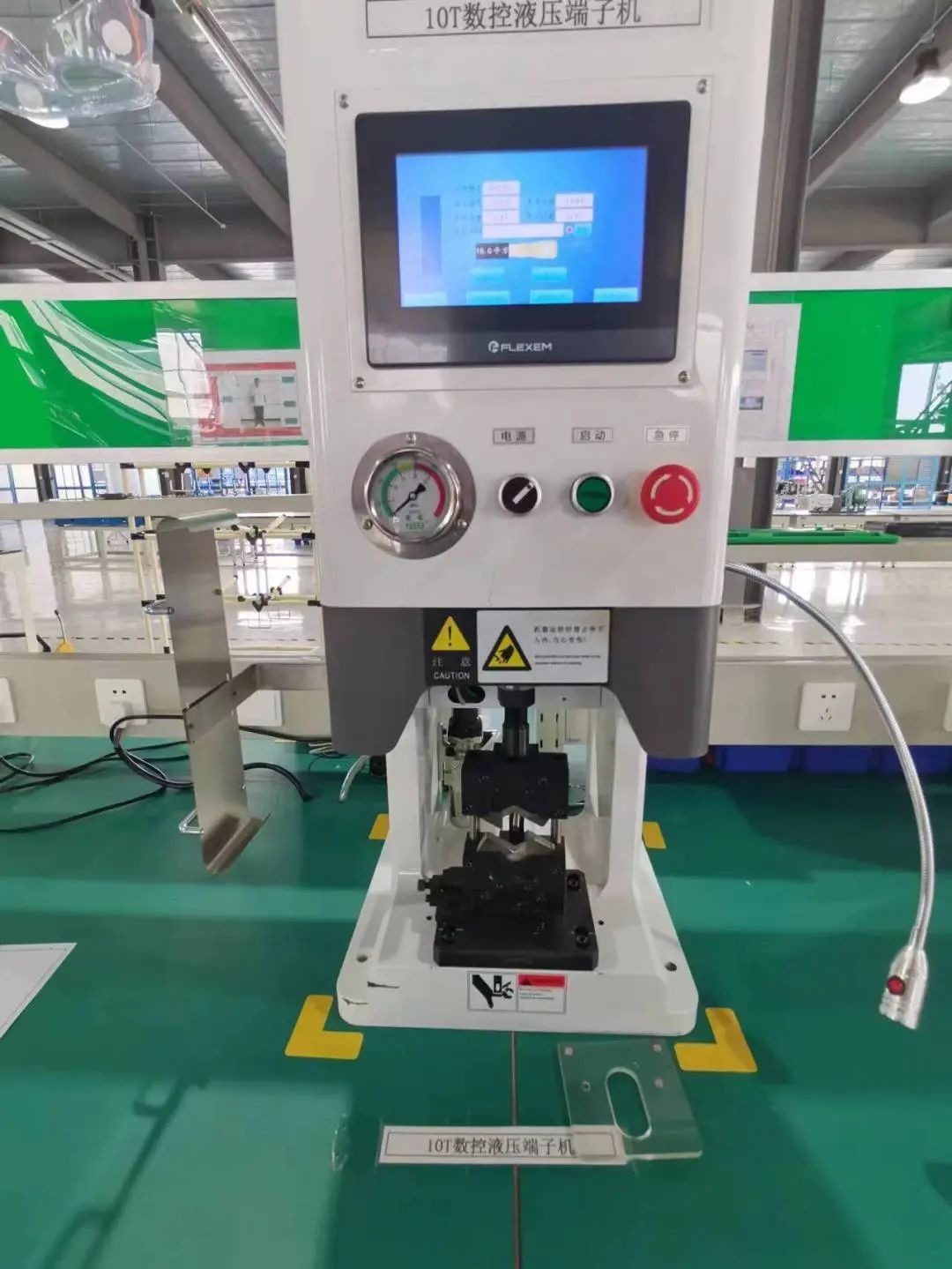
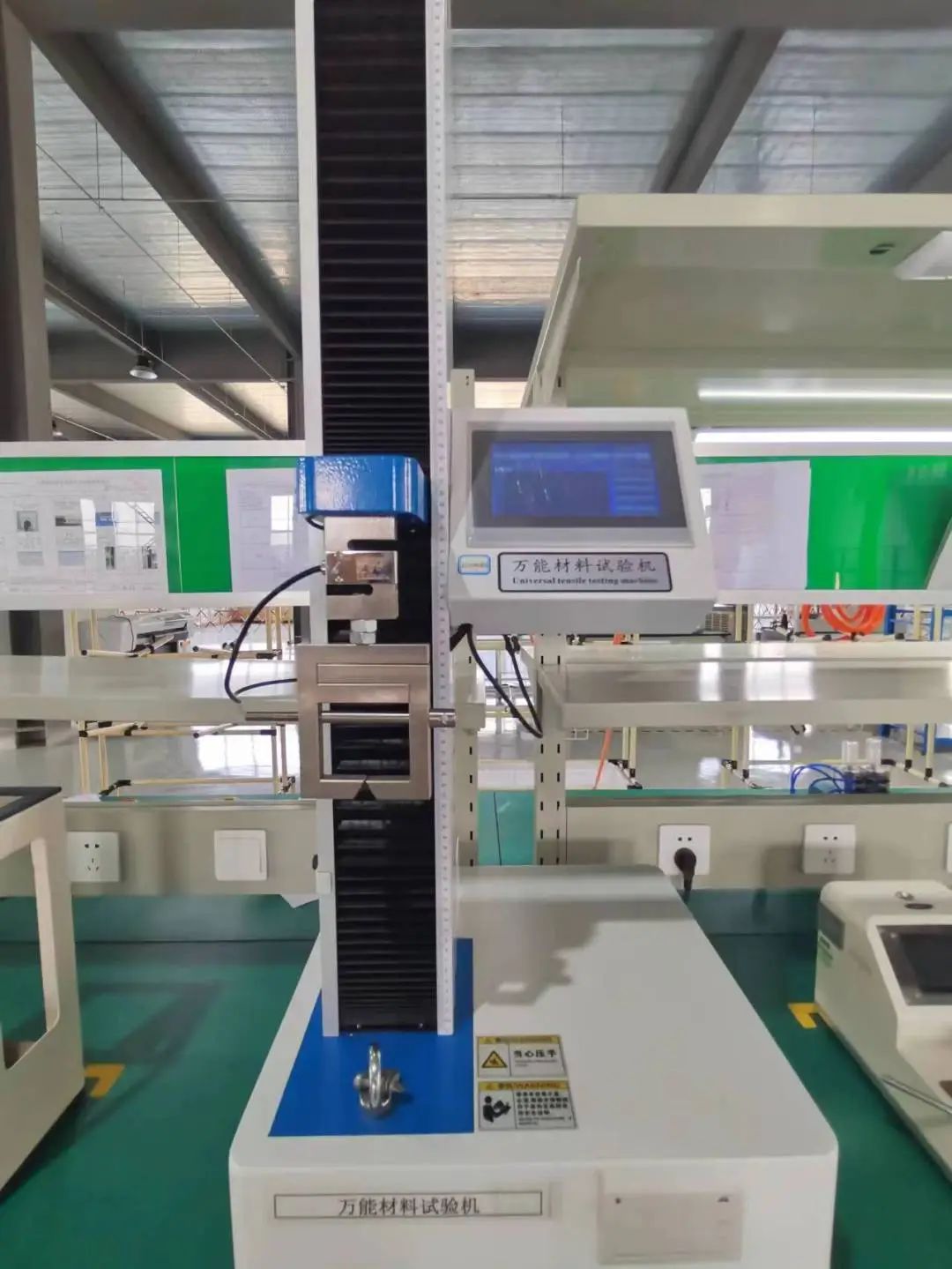
Terminal pull-test machine (left) and insulation testing equipment (right).