Overview
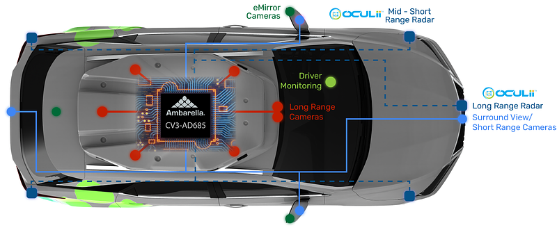
Compared with cameras used for ADAS perception systems, cameras installed inside the cockpit have simpler functional characteristics and lower performance requirements. For example, an OMS passenger monitoring camera typically achieves good results at 5 MP. OMS can also be used for in-cabin conferencing and child detection. DMS driver monitoring systems, SVC 360 surround cameras, and DVR dashcams are cameras shared between the autonomous driving domain (ADC) and the cockpit domain (CDC). The following sections summarize these camera types.
Key considerations for automotive cameras are mounting location and distance to the ISP processing chip. For cameras below 2 MP, image data is often output directly in YUV format without a dedicated ISP. For cameras above 2 MP, devices typically output raw data and require an ISP for image processing. Because many cameras may be used, placing an ISP with every camera would be costly. It is common to centralize ISP processing inside the CDC cockpit controller and transport camera raw data over high-speed transmission lines to a centralized ISP. This requires a high-speed video transport bus.
As described in discussions of high-speed audio/video interfaces, common solutions use GMSL or FPD-Link to transmit remote camera raw data into the CDC. Emerging options include MIPI-A PHY and ASA. Serializer/deserializer (SerDes) chips are typically paired: a serializer at the camera end and a deserializer at the CDC end. Cable runs can reach up to about 10 meters, rarely exceeding 15 meters.
OMS: Occupant Monitor System
OMS (occupant monitor system) is used for passenger and rear-seat detection. Several regions already require in-vehicle child presence detection by regulation. Euro NCAP added evaluation for child presence detection starting in 2023, with detailed requirements. The United States is enacting regulations to require child presence detection preinstalled in new vehicles, with broad implementation expected in 2025. Related standards in the Chinese market are under development.
OMS cameras can partially satisfy child presence detection requirements. To improve detection accuracy, some systems add vital-sign detection radars such as UWB or millimeter-wave radar. Typical practice places a primary OMS camera (5 MP or even 8 MP) near the front rearview mirror and adds 2 MP rear OMS cameras above second- and third-row seats. By applying face recognition, motion capture, and liveness detection AI algorithms, OMS improves in-cabin perception.
OMS also supports in-cabin video conferencing, secure payment authentication, and multimodal fusion with intelligent assistants. To operate under any cabin lighting, OMS typically supports RGB-IR dual-band operation and uses infrared illumination. IR is used at night and RGB during daytime.
TOF
TOF stands for time of flight. TOF 3D imaging transmits light pulses to the target and measures the round-trip flight time of returned light to determine distance. It is similar in principle to 3D LiDAR, but while LiDAR scans point by point, a TOF camera captures depth for the whole image simultaneously. TOF systems consist of a light source, optics, sensor, control and processing circuits, and so on. Compared with binocular stereo systems, TOF uses a fundamentally different 3D imaging mechanism: binocular systems rely on stereo correspondence and triangulation, whereas TOF measures time-of-flight of reflected light.
Because TOF emits and measures many points, it typically has low spatial resolution and high power consumption. Due to limitations of the light emission, TOF resolution rarely exceeds 640x480, and power consumption can be an order of magnitude higher than structured light systems.
Stereo Structured Light + RGB
Stereo structured light uses binocular stereo vision, mimicking left-right disparity of human eyes. Two infrared cameras capture images from left and right viewpoints, then compute disparity between corresponding points and apply triangulation to obtain depth. The structured light projector emits an infrared dot pattern to enhance surface texture, which the IR cameras capture for subsequent algorithmic processing.
The four basic steps of a stereo system are:
- Camera calibration: single-camera intrinsic calibration and stereo extrinsic calibration to obtain focal length, principal point, distortion coefficients, and the rotation and translation between camera coordinate systems.
- Stereo rectification: correct the raw images so they lie on the same plane and corresponding scanlines are aligned for easier matching.
- Stereo matching: match pixels between rectified images to identify corresponding points.
- Depth computation: compute disparity for each matched pixel by triangulation, producing a depth map.
Stereo systems require modest hardware: two IR cameras plus an SoC with a DSP can compute depth maps. However, they require a baseline distance between cameras, which constrains installation and increases sensitivity to scene texture and lighting.
Monocular Structured Light
Structured light projects an encoded near-infrared pattern onto the scene using an infrared laser. A dedicated IR camera captures the deformed pattern; algorithms convert the pattern deformation into depth information to reconstruct 3D structure. Structured light typically uses an invisible IR wavelength and patterns are coded to extract position and depth from returned images.
Compared with TOF, structured light consumes less power since it needs to illuminate only a small region. It offers higher resolution and accuracy than TOF at lower cost. Compared with stereo structured light, monocular structured light allows a smaller baseline, which is easier to deploy in cabins. It also works in low-light conditions, making it well suited for in-cabin use. However, in very strong ambient light, the projected speckle pattern can be overwhelmed and may fail.
OMS Vision Options
In-cabin perception benefits significantly from OMS. Beyond voice recognition, multimodal perception increasingly relies on vision. Depth-informed gesture recognition, facial expression and emotion recognition, and mouth movement detection enhance the capabilities of in-vehicle assistants and improve user experience.
Comparing the options above, aside from monocular RGB+IR (which lacks depth), the other three are depth-capable camera choices. Stereo structured light plus RGB requires high computational resources, impacting real-time performance; higher resolution and precision increase computational complexity. A pure stereo approach is sensitive to lighting and surface texture; the RGB channel is mainly used to overlay or validate depth results.
TOF offers low algorithmic complexity and high frame rates (up to 120 fps) with modest processing needs, but lower resolution and depth precision and higher hardware cost due to multi-point laser emission.
Monocular structured light addresses stereo matching complexity and robustness in most environments, but can be vulnerable to strong direct sunlight, which may wash out the projected pattern.
DMS: Driver Monitor System
DMS (driver monitor system) continuously monitors driver state to detect fatigue and risky behaviors. When the driver yawns, squints, smokes, or uses a handheld phone, the DMS analyzes the behavior and issues alerts via audio or indicator lights to warn the driver and correct unsafe actions.
DMS primarily belongs to the autonomous driving domain (ADC) rather than the cockpit domain (CDC). However, because DMS is normally mounted below the A-pillar facing the driver, it is also considered an in-cabin camera.
DMS commonly uses a 2 MP infrared camera and does not require RGB. The captured image must be machine-readable so AI models can accurately assess driver state rather than being optimized for human viewing. A 2 MP infrared camera with IR illumination is usually sufficient to capture facial features under all lighting conditions.
Note that both DMS and OMS use IR illumination. A dedicated IR light synchronization signal should prevent DMS and OMS IR illuminators from operating simultaneously to avoid overexposure.
Advanced DMS perception includes eye tracking, facial expression and emotion monitoring. Multimodal recognition combined with vehicle assistants will expand to include lip-reading and other AI-based recognition.
Dashcams (DVR)
Vehicle DVRs, or dashcams, include OEM-installed (front-fit) and aftermarket devices. Aftermarket dashcams are standalone units that use consumer-grade chips to encode and store audio/video from an onboard camera. Because they are not subject to automotive qualification, their reliability does not meet automotive-grade standards.
OEM dashcams must meet automotive-grade requirements and are installed during vehicle production, with lifetime and reliability aligned to automotive electronics standards.
OEM dashcam functions can often reuse ADAS cameras. Typically, a DVR records a forward wide-field-of-view camera (about 120° FOV) plus SVC 360 surround camera data. To support day/night recording and transitions such as tunnel entry, forward and surround cameras typically require HDR capability, and the ISP must support HDR.
Surround View Cameras (SVC)
SVC (surround view cameras) are usually mounted at the front, rear, left mirror, and right mirror positions. SVC is a multi-camera system that provides a 360-degree view by fusing multiple camera images into a top-down "bird's-eye" perspective, aiding parking and nearby obstacle awareness.
Digital Mirror Systems (CMS)
Regulation and Overview
CMS (camera monitor system) replaces conventional glass mirrors with electronic displays. It is also referred to as electronic side mirrors, virtual mirrors, or camera-based rearview mirrors. ISO names this class Camera Monitor Systems.
Some production vehicles have implemented CMS with OLED displays and camera modules. Global regulations permitting full replacement of glass mirrors are currently in Japan and Europe. Relevant regulations include UN ECE R46-2016 on indirect vision devices and ISO 16505-2019 containing ergonomic and performance requirements and test procedures for camera monitor systems. IEEE P2020 aims to standardize automotive camera image quality tests for both human-vision and computer-vision applications.
CMS requires dedicated HDR-capable cameras, transmission channels, and displays. Camera resolution and frame rate typically reach up to 2 MP at 60 fps or 4 MP at 30 fps. The cost and integration complexity remain significant.
National standard GB 15084-2022 allowing digital mirrors came into effect on 2023-07-01 in the Chinese market.
CMS Performance Requirements
For passenger vehicles, it is important to distinguish Class I and Class III mirrors. Class I refers to electronic interior rearview mirrors that display video from a rear camera on an in-cabin monitor. Class III refers to electronic exterior mirrors that replace left and right side mirrors and display side camera video on interior screens.
GB 15084-2022 specifies detailed CMS performance and test methods, including:
- Brightness adjustment: monitors must support manual or automatic brightness adjustment according to ambient conditions.
- Directional uniformity: limit image brightness attenuation when viewed from different directions to ensure sufficient visibility.
- Luminance and contrast reproduction: evaluate across typical scenes such as direct sunlight, diffuse daylight, dusk, and night conditions.
- Gray level and color reproduction: display at least eight gray levels and meet color reproduction tests per ISO 16505.
- Veiling glare: limit veiling brightness so it does not exceed 10% of the maximum brightness of the light source image causing the veiling.
- Halos and lens flare: halo and flare regions must not exceed 25% of the displayed image area using ISO 16505 test methods.
- Point sources: require distinguishability of two rear car headlights at night; discovery coefficient must be at least 2.7 or contrast coefficient at least 0.12.
- Sharpness, depth of field, and geometric distortion: specify test criteria and validation methods per ISO 16505.
- Frame rate: at least 30 fps; in low light or low vehicle speed, it may drop to 15 fps.
- Imaging time and system latency: display imaging time should be under 55 ms; system delay from external event to in-cabin monitor output should not exceed 200 ms.
Meeting OEM requirements for CMS requires system-level analysis across camera optics, control chips, ISP processing, and displays. Mechanical, optical, and electronic integration are required to achieve compliant performance.
CMS System Architectures
CMS implementations generally follow two paradigms: an MCU-based solution and an SoC-based solution. The MCU approach is simpler, lower cost, and lower latency. The SoC approach provides richer features but at higher cost and higher latency. The central processing task in CMS is ISP. If the camera stream is used only for display, an MCU can be sufficient for ISP. If application-layer features (for example, blind spot detection or door-open warnings) are required on top of the ISP output, an SoC is needed.
In MCU solutions, the ISP can be integrated into the display panel (preferred by display suppliers) or into the camera module (preferred by camera suppliers). The MCU approach avoids a separate CMS controller. In SoC solutions, ISP is typically in a dedicated CMS controller, or can be integrated into a domain controller for driving or cockpit domains in the future.
Three common architecture choices are:
- ISP integrated in the display, with camera modules separate. Display suppliers embed processing on the display PCB to handle incoming camera images, fitting a modular display-centric approach.
- ISP integrated in the camera housing, with in-cabin display separate. Camera suppliers embed processing inside the camera housings, allowing smaller system modules and enabling the camera modules to adapt to different displays. Camera raw data is processed at the camera and then displayed inside the cabin.
- ISP centralized in the cockpit domain controller (CDC) and camera reuse. This approach uses a central SOC with strong ISP capability to process raw camera inputs and yields the lowest component cost, since only the display is added. However, achieving functional safety requirements for Class III mirrors in this centralized scheme is a challenge, which limits immediate commercialization; it remains a feasible direction for future development.