Overview
Even without considering the shift from internal combustion engines to battery electric vehicles (BEVs), modern vehicles present daunting electrical demands. Every onboard device—from climate control and seat heaters to lighting and infotainment—requires power, and the conductors that deliver that power must have sufficient gauge to carry the required current.
Large numbers of devices and their associated wiring create significant packaging and routing challenges. As vehicle manufacturers focus on improving fuel economy and electric vehicle range, the weight and cost of all that wiring are under increasing scrutiny.
One way to reduce conductor gauge, weight, and cost is to move from a 12V electrical architecture to a 48V-based architecture. However, manufacturers shifting to 48V must pay special attention to several key design considerations to ensure system safety and reliability.
Origin of 12V
This is not the first major inflection in vehicle electrical architecture. About 70 years ago the automotive industry faced a similar issue, though on a smaller scale. Before the 1950s most vehicles used 6V batteries and electrical systems. Rising material content and copper prices drove a shift to 12V worldwide over the course of a decade.
Because electrical power follows P = V × I, doubling the voltage means devices can draw the same power at half the current. Current determines conductor diameter since thicker conductors have lower resistance and can safely carry higher current. Conversely, lower current can flow through finer wire, allowing smaller conductors, terminals, and connectors, all of which reduce weight and material cost.
Raising system voltage is therefore an important tool for addressing the growth in functionality, packaging, weight, and cost. Since the 1950s the average current flowing in 12V systems has increased by more than 650%, so another architectural overhaul is timely.
Why 48V?
With 12V becoming limiting, many vehicle manufacturers see 48V as the most logical next step. It strikes a balance: increasing voltage fourfold reduces current fourfold while remaining well below the 60V threshold commonly cited for basic touch-safety protections. With a 48V system, designs can be protected up to about 60V in overvoltage scenarios.
Besides enabling notably smaller terminals and wiring, higher voltage reduces losses. Ohm's law and power loss via resistance give P = I^2R, so because current in a 48V architecture is one quarter of the 12V current, theoretical power loss due to resistance in the power delivery system is reduced by a factor of 16. In practice resistance increases as conductor size is reduced, so actual losses depend on system optimization. Still, with lower current, voltage drops along conductors are smaller when driving loads. Some devices, such as starter motors, also benefit from higher operating voltage: they can use less copper and deliver more torque while possibly requiring a smaller package.
Design Considerations
If the transition from 12V to 48V offers these advantages, why has the automotive industry not fully switched? The inertia behind 12V is strong. The industry has used 12V for seven decades, and moving to 48V requires new designs and rework for many components. Not all devices will migrate to 48V: lower-power devices may remain at 12V, and as the market shifts toward full electric vehicles, some devices will operate at battery pack voltages, often 400V or 800V.
Where 48V makes sense, designers must take several steps to ensure safety and reliability.
Sealing Requirements
If 48V connectors are accidentally exposed to electrolytes such as saltwater, electrochemical corrosion reactions will attack terminals more aggressively than at 12V. Designers should consider whether connectors must be sealed and, where sealing is required, use proven, robust sealing techniques.
Arc Prevention
Arcing is a risk related to voltage level and spacing between terminals. Arc temperatures range from about 2800°C to 19000°C. While 12V circuits can produce small arcs when opened, those arcs usually extinguish quickly. At 48V, arcs may persist longer and cause catastrophic damage to terminals and connectors. To prevent this, terminals inside connectors should be properly spaced and particular care taken to avoid thermal disconnects.
Avoid intermittent contacts, fretting corrosion, or terminal pull-out. Unstable terminal contact can cause microarcs that damage plating or terminal base metal, resulting in high resistance or welded joints.
Use effective secondary terminal locks to ensure terminals are fully retained in connectors. Terminal pull-out can cause slow or intermittent power interruptions that lead to destructive arcing.
Always remove 48V power before servicing 48V connections. Slowly opening live connections can extend arcing and cause thermal damage.
Voltage Separation
Special precautions are required in mixed-voltage systems to ensure current cannot flow from 48V equipment into 12V equipment. Isolation of circuits operating at different voltages is the preferred solution.
A conservative approach is to avoid connectors carrying both 48V and 12V circuits. If mixed voltages must share a connector, partition the connector to provide physical separation of voltages. When routing wiring harnesses, keep 48V and 12V circuits separate where possible, although this is not always feasible.
Avoid routing 48V conductors in areas where wire insulation could be damaged; use protective coverings where needed. Damaged insulation can create arcs to grounded metal in the vehicle. Also avoid using the same ground stud for devices at different voltages. If a ground stud becomes loose or separated, current may flow from 48V devices into 12V systems through shared connections.
Creepage and Clearance
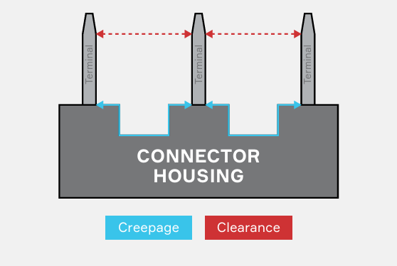
Although 48V is considered low voltage, arcing remains a risk. To reduce risk, connector designs must meet appropriate creepage and clearance requirements.
Creepage: the shortest distance between two conductive parts along the surface of an insulating material.
Clearance: the shortest "line-of-sight" distance through air between conductors.
Creepage and clearance considerations
When assessing existing connectors or designing new connectors for 48V systems, use the IEC 60664-1 edition 3.0 (2020-05) standard to determine appropriate creepage and clearance distances for terminal positions within a connector. Apply the standard with protection up to 60V, the upper limit of the overvoltage range.
Use appropriate pollution degree ratings for sealed and unsealed connectors and select material groups according to the comparative tracking index (CTI) defined in IEC 60112/UL 1950. CTI indicates the maximum voltage a material can withstand under 50 drops of polluted water without forming a conductive path under electrical stress, humidity, and contamination. Most automotive connectors and terminals with traditional terminal spacing will meet clearance requirements, but some connectors and terminals may require subtle design changes to meet creepage requirements.
Adoption and Enabling Technologies
48V-based electrical architectures offer many benefits but require careful adherence to design guidelines to mitigate risks associated with higher voltage.
As 48V devices become more common in mixed-voltage vehicle architectures, advanced techniques can help ensure the architecture supports them. For example, harness automation can significantly reduce the risk of terminal pull-out. Advanced software algorithms in 48V solid-state electrical centers may be able to detect and mitigate arcing. Defining net architectures for various vehicle types will help establish 48V power and backup systems that meet all functional safety requirements. Printed circuit board and component designs can make distribution modules smaller, cooler, and more cost-effective at 48V.
48V Color Coding
In the automotive industry, orange connectors and wires are synonymous with high voltage, typically any voltage above 60V. This color coding clearly identifies components that should not be touched without appropriate safety training and personal protective equipment.
Although 48V is not considered high voltage, the increased risk of arcing and related phenomena has led to a recommendation that 48V connectors be color coded. Light blue is the preferred color.
This recommendation traces back to electric forklifts, which have long relied on batteries at different voltages and therefore developed color guidelines for battery connectors to avoid mismatches. Today, the blue connector standard for 48V connections has been adopted by many sectors and is likely to be used for 48V automotive connectors and wiring.
printed circuit board designs and other component choices should follow established electrical and safety standards when implementing 48V distribution and modules.