1 Fault symptoms
A 2022 Zeekr 001 with approximately 12,000 km, equipped with TZ220XSA01 dual motors, experienced a total electrical shutdown while driving. The owner reported that after startup the instrument cluster displayed a charging fault. After driving for a while the instrument cluster displayed both a charging fault and a powertrain fault, then the vehicle lost all electrical power and propulsion.
2 Diagnosis
On receipt, the 12V battery voltage was measured at 3.3 V, indicating severe discharge. After charging the vehicle for 6 hours the 12V battery measured 14.1 V. After starting the vehicle the 12V battery voltage quickly fell to 11.75 V, which was abnormal. The instrument cluster displayed the message: "Battery voltage too low, please park safely, please contact Zeekr official after-sales."
A diagnostic scanner was connected and a full-vehicle fault scan found multiple stored fault codes in the CDD (charger and DC/DC module) control unit: POE9900 - DC/DC converter voltage sensor "C" circuit voltage high; U144801 - charger and DC/DC module (CDD) general electrical fault; B164B00 - internal communication error.
Reading the CDD control unit datastream showed the DC/DC activation request was active, with no derating and an input voltage of 14.2 V. However, the measured 12V battery voltage remained at 11.75 V, indicating the CDD output voltage was not correct and that the CDD control unit was not operating properly.
Following the vehicle wiring diagram for the affected model, the low-voltage connector A of the CDD was unplugged and the male and female terminals were inspected; no loose or damaged pins were found. Using a specialized tool to check the terminals revealed no enlarged pin holes. Measurements from the wiring diagram showed A1 (KL30) to chassis ground voltage at 12.71 V, normal. A2 (GND) to chassis ground resistance was 0.3 Ω, normal. The AC charging inlet terminals showed no visible abnormalities. Measurements of the E1 (CC) and E4 (CP) pins to chassis ground and between E1 and E4 were within expected values. End-to-end resistance between the AC inlet CC and CDD E1, and between AC inlet CP and CDD E4, was 0.2 Ω, normal. These checks indicated the CDD power and ground were intact and the AC charging circuit and charging harness to the 12V battery had no external faults.
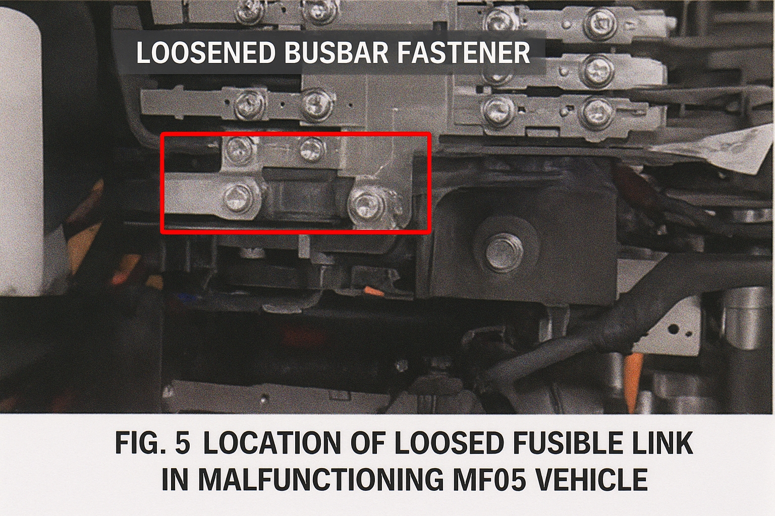
According to the CDD circuit diagram, the high-current charging feed from the MF05 MEGA 350A fuse to the CDD G1 terminal measured 0.3 Ω, which was normal. The MF05 fuse fastening was inspected and showed no issues.
The CDD module software was synchronized and an attempt was made to reload the CDD control unit, but the fault persisted. After excluding all external wiring, connector, fuse, and charging-circuit causes based on fault codes and measurements, the remaining likely cause was an internal component failure within the CDD control unit. The manufacturer does not permit disassembly and repair of the CDD, so the CDD assembly was replaced. After replacement and synchronizing the CDD software, the CDD output to the 12V battery returned to normal voltage and the vehicle fault was resolved.
3 Repair summary
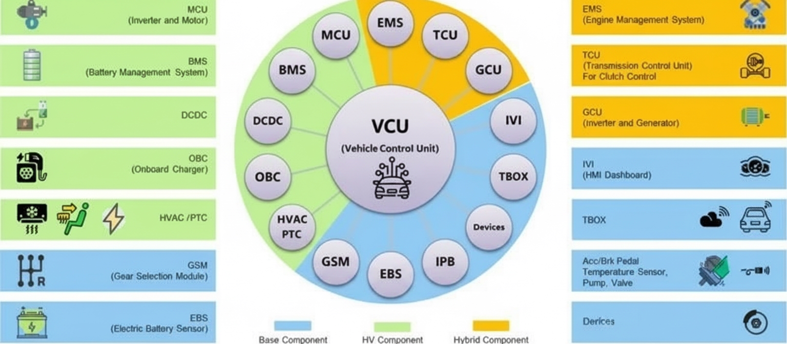
The CDD control unit, also referred to as the ODP, integrates the OBC AC charger, the DC/DC converter, and the PDU high-voltage distribution into a single module. The OBC converts AC from slow charging to DC for the traction battery. The DC/DC converter steps down the high-voltage traction battery output to charge the 12V battery. The PDU controls precharge-related circuits.
In this case, the immediate symptom was a discharged 12V battery that caused multiple control units to stop functioning. The root cause was an internal component failure inside the CDD control unit, which prevented the DC/DC converter from charging the 12V battery from the traction battery. The resulting 12V battery discharge caused low-voltage modules to become inoperative and produced the reported total power loss.