Why Is Identifying Through-Hole Components Essential for Newcomers?
If you’re just beginning your journey into the world of electronics, mastering through-hole component identification is a foundational skill. This guide will walk you through the crucial aspects of recognizing resistors, capacitors, interpreting component codes, understanding polarity, and differentiating between axial and radial lead components. Whether you are assembling your first circuit board or troubleshooting an existing project, a solid grasp of these fundamentals is key to building functional and reliable electronics. Let’s explore these essential details in a clear, step-by-step manner.
What Defines a Through-Hole Component?
Through-hole components are electronic parts characterized by their metal leads, which are designed to be inserted into pre-drilled holes on a printed circuit board (PCB) and then soldered securely. Unlike the smaller surface-mount components (SMDs) that are soldered directly onto the board's surface, through-hole components are larger and generally easier for beginners to handle. They are widely used in educational kits, for pcb prototype manufacturing, and in applications where robust durability is a primary concern.
This guide will concentrate on how to effectively identify these components, interpret their various markings, and ensure they are correctly placed on a PCB. By the end, you will be confident in identifying through-hole resistors, recognizing different types of through-hole capacitors, and much more.
Why Is Accurate Component Identification So Important?
Accurate identification of through-hole components is absolutely critical for the successful construction of any electronic circuit. Using an incorrect component or installing one improperly can lead to a range of issues, including circuit malfunction, short circuits, or even irreversible damage to other parts. For those new to electronics, learning how to correctly read component markings, understand polarity, and differentiate lead types will save significant time and prevent potentially costly mistakes. Let’s break down the main areas of focus for effective through-hole component identification.
How to Identify Through-Hole Resistors: Deciphering Color Bands
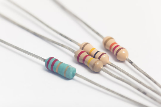
Resistors are among the most frequently encountered through-hole components, serving to regulate current or divide voltage within a circuit. Identifying a through-hole resistor primarily involves interpreting its color bands, which encode its resistance value and tolerance.
Most through-hole resistors feature either four or five color bands. Here’s a breakdown of how to read them:
● First Band: This band indicates the first significant digit of the resistance value.
● Second Band: This represents the second significant digit.
● Third Band: For a four-band resistor, this acts as a multiplier. In a five-band resistor, it provides the third significant digit.
● Fourth Band: This band specifies the component’s tolerance, indicating the precision of its resistance value (e.g., ±5% or ±10%).
● Fifth Band (if present): This additional band typically denotes the temperature coefficient or an extra tolerance factor, offering more precise information.
For example, a resistor with bands of Brown, Black, Red, and Gold signifies a resistance of 1,000 ohms (1 kΩ) with a tolerance of ±5%. Numerous online color code calculators and charts are available to help you practice and confirm these values. Resistors are typically axial components, meaning their leads extend from opposite ends of a cylindrical body. When placing them on a PCB, their orientation is not critical as resistors are non-polarized.
Understanding Through-Hole Capacitor Types and Markings
Capacitors are vital components that store and release electrical energy in a circuit. Through-hole capacitors come in several types, each designed for specific applications and featuring distinct identification markings. Let's explore the primary types and how to recognize them.
Common Through-Hole Capacitor Types
● Ceramic Capacitors: These are small, often disc-shaped capacitors, commonly employed in high-frequency circuits. They are non-polarized, allowing them to be installed in any orientation. Their capacitance value is usually indicated in picofarads (pF) using a three-digit code. For example, a marking of "104" translates to 10 followed by four zeros, or 100,000 pF, which is equivalent to 0.1 μF.
● Electrolytic Capacitors: These are larger, cylindrical capacitors primarily used for filtering and power supply applications. They are critically polarized, meaning correct orientation is essential for their proper function and to prevent damage. The negative lead is typically marked with a stripe or a minus sign, and the positive lead is often longer. Their capacitance value (in microfarads, μF) and voltage rating are explicitly printed on the body, such as "100μF 16V."
● Film Capacitors: Often rectangular or cylindrical, film capacitors are non-polarized and used for applications such as noise suppression and precise timing circuits. Their markings may directly state the capacitance value, like "0.047 μF," or they might use a coded system similar to ceramic capacitors.
Understanding these different types of through-hole capacitors is crucial for selecting the appropriate component for your circuit and ensuring it is installed correctly to avoid component failure or circuit damage.
Deciphering Through-Hole Component Codes Beyond Resistors and Capacitors
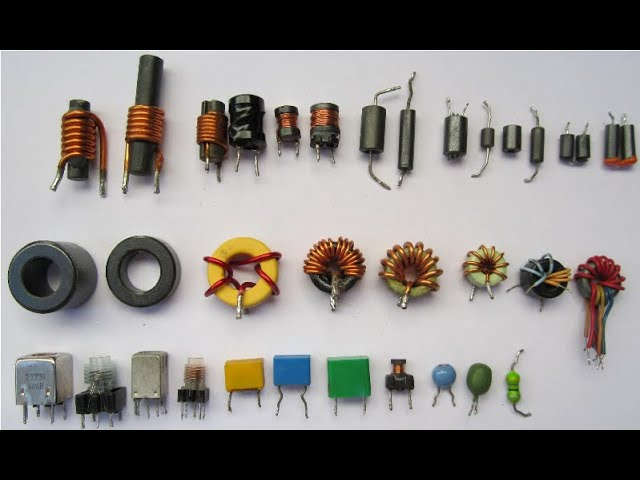
Beyond resistors and capacitors, many other through-hole components—such as diodes, transistors, and inductors—bear printed codes or distinct markings that convey their specific characteristics. While each component category may have its unique identification system, here are some general guidelines for interpreting through-hole component codes:
● Diodes: Look for a prominent band or stripe on one end of the diode's body; this typically denotes the cathode (negative terminal). Part numbers, such as "1N4148," may also be printed for precise identification.
● Transistors: These components often feature a part number printed directly on their casing, for instance, "2N2222." The correct orientation of their leads (base, collector, emitter) must strictly match the requirements of the circuit design.
● Inductors: Similar to resistors, inductors may use a system of color bands or display direct value markings, typically in microhenries (μH).
When component markings are ambiguous or unclear, always consult the component's official datasheet. Datasheets provide comprehensive specifications, detailed pin configurations, and essential usage guidelines to ensure proper application.
The Importance of Through-Hole Component Polarity
Polarity refers to the distinction between the positive and negative terminals of a component. Incorrect orientation of polarized components can lead to immediate damage to the component itself or the entire circuit. While not all through-hole components are polarized, for those that are, accurate placement is absolutely essential. Here’s how to manage through-hole component polarity:
● Electrolytic Capacitors: As previously noted, the negative side is clearly indicated by a stripe or an arrow on the component body. The positive lead is generally longer. Always ensure these align with the corresponding markings on your PCB.
● Diodes: The cathode (negative terminal) of a diode is marked with a band. Current is designed to flow from the anode to the cathode, so it's critical to ensure this direction aligns with your circuit design.
● LEDs (Light-Emitting Diodes): Similar to diodes, LEDs have a longer lead that corresponds to the anode (positive terminal) and a shorter lead for the cathode (negative terminal). Some LED packages also feature a flattened edge on the plastic body on the cathode side, providing an additional visual cue.
Non-polarized components, such as standard resistors and ceramic capacitors, can be inserted in any direction, making them generally easier for beginners to work with.
Differentiating Axial and Radial Lead Components
Through-hole components are further categorized by their lead configuration, which dictates how they are mounted onto a PCB. Understanding the distinction between axial and radial lead components is fundamental for correct identification and proper placement.
Axial Lead Components
Axial lead components feature leads that extend from both ends of the component body, running parallel to its central axis. Common examples include most resistors, diodes, and certain types of capacitors. These components are typically laid flat or have their leads bent to fit into holes across a span on the PCB, connecting two distinct points.
Radial Lead Components
Radial lead components, in contrast, have leads that originate from one side of the component body, extending perpendicular to its axis. Electrolytic capacitors and some LEDs are typical examples. These components are designed to stand upright on the PCB, with their leads inserted into adjacent holes.
Being able to distinguish between axial and radial lead components is crucial for understanding their correct positioning on a circuit board, which in turn ensures a neat, organized, and functionally sound assembly.
Practical Tips for Beginners in Component Identification
Developing proficiency in identifying through-hole components becomes much easier with the right tools and consistent practice. Here are some practical tips to help you hone your skills:
● Utilize a Multimeter: A multimeter is an invaluable tool for testing resistance, capacitance, and diode polarity, especially when component markings are unclear. For example, measuring a resistor’s value can confirm its color band reading, ensuring it’s close to 1 kΩ.
● Keep Reference Charts Handy: Always have a resistor color code chart and a capacitor code table readily accessible for quick lookups and confirmations.
● Organize Your Components: Sort and store your components by type and value in clearly labeled containers. This practice prevents mix-ups and streamlines your workflow during projects.
● Double-Check Polarity: Before soldering any polarized components, meticulously verify their orientation against the PCB silkscreen markings or the circuit schematic.
● Practice with Kits: Start with beginner-friendly electronics kits. These often include a variety of through-hole components and provide clear, step-by-step pcba assembly instructions, offering valuable hands-on experience.
Common Mistakes to Avoid During Through-Hole Component Identification
Even with careful attention, beginners can fall into common traps. Being aware of these pitfalls can help you avoid costly errors in your electronics projects.
● Misinterpreting Color Bands: Confusing subtle color differences, such as brown and red, can lead to incorrect resistance values. Always ensure good lighting and use magnification if necessary to accurately read the bands.
● Neglecting Polarity: Installing a polarized component like an electrolytic capacitor or a diode backward is a serious mistake that can result in component failure, overheating, or even an explosion. Always double-check polarity markings.
● Mixing Up Lead Types: Incorrectly bending axial leads or misplacing radial components can make your circuit appear messy and, more importantly, prevent it from functioning as intended.
● Overlooking Voltage Ratings: Using a capacitor with a voltage rating that is lower than the circuit’s operating voltage (e.g., a 10V capacitor in a 12V circuit) can cause the capacitor to break down, potentially damaging other components.
Conclusion: Mastering the Art of Through-Hole Component Identification
Acquiring proficiency in through-hole component identification is a fundamental skill for anyone embarking on a journey in electronics. From accurately reading through-hole resistor color bands to recognizing various through-hole capacitor types and their crucial polarity, each step builds your capacity to design and assemble reliable circuits. By understanding how to decipher component codes and distinguish between axial and radial lead configurations, you will effectively sidestep common errors and gain confidence in all your electronics projects.
Begin with simple projects, practice consistently, and leverage the tools and tips provided in this guide to sharpen your skills. With dedication and time, identifying and working with through-hole components will become second nature, paving the way for you to tackle more intricate and exciting electronic designs. If you are ready to advance, explore resources and services for PCB assembly and prototyping to transform your innovative ideas into tangible realities.