Overview
This chapter uses the AP525 as an example to introduce the instrument hardware interfaces, the AP test software interface, and the standard sequence test workflow. After reading this chapter, the Telink TLSR9518A EVB will be used as the DUT to test audio metrics under different modes.
1. AP525 Hardware Panel
The AP525 front panel is shown below and is divided into six interface modules (configurations may vary by instrument).
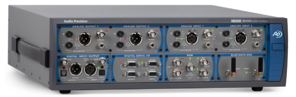
Figure 1 Front panel diagram
1. Analog outputs
Analog OUTPUT 1/2, two channels.
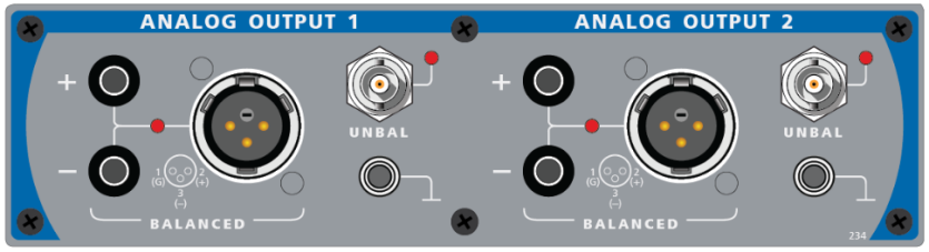
Figure 2 Analog output interface panel
2. Analog inputs
Analog INPUT 1/2, two channels.
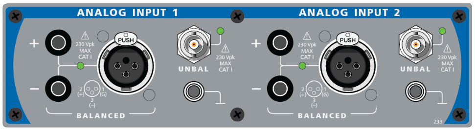
Figure 3 Analog input panel
Digital serial I/O
Digital serial signal input/output. Hardware connector: HD-15. Supported formats: I2S, DSP (bit-wide pulse), custom format.
The interface pinout is shown below.
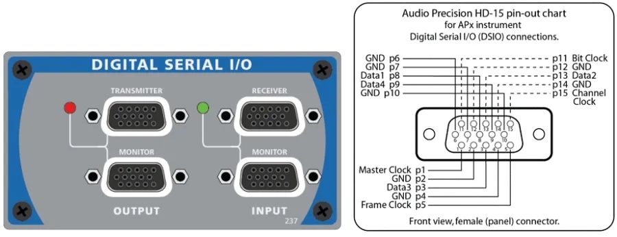
Figure 4 Digital serial I/O panel and interface definition
3. Bluetooth audio testing
Bluetooth DUO interface used for Bluetooth audio testing. Supports A2DP, AVRCP, HFP and other Bluetooth profiles.
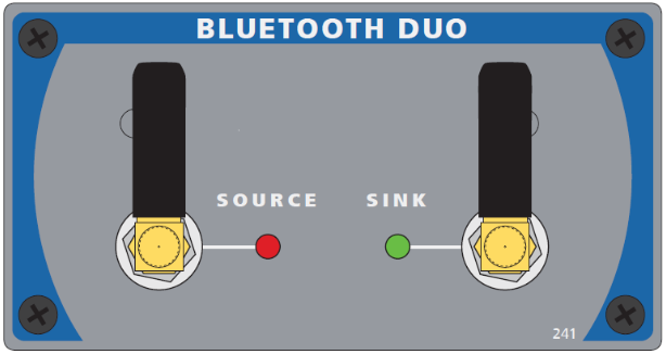
Figure 5 Bluetooth test interface panel
Digital INPUT/OUTPUT
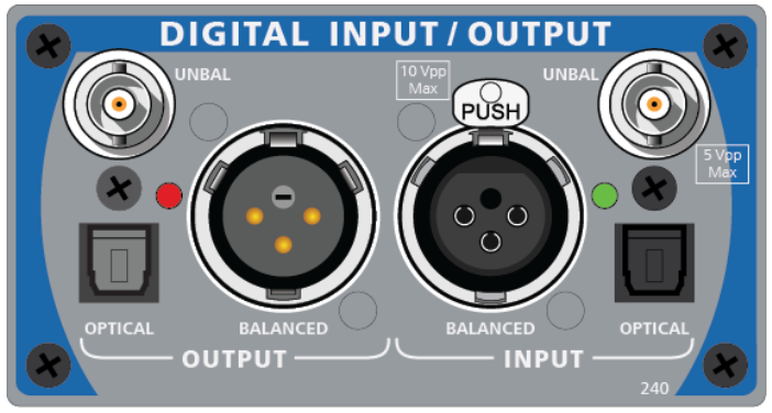
Figure 6 Digital input/output panel
4. PDM (Pulse Density Modulation)
Hardware connector: BNC.
Bit clock support range: 128 kHz to 24.576 MHz.
Vdd output range: 0 V to 3.6 V. Max output load capacity: 15 mA.
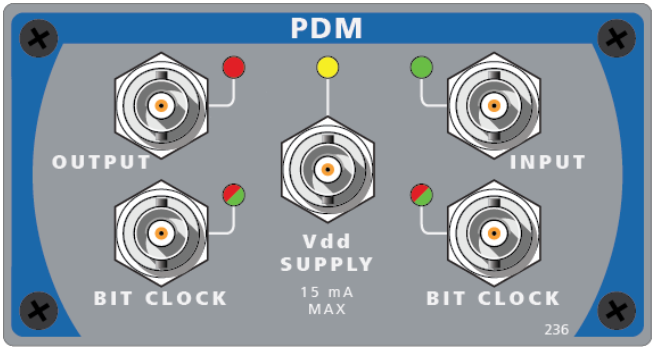
Figure 7 PDM interface panel
2. AP Software Interface
The AP software has two test-mode interfaces: Bench Mode and Sequence Mode.
- Bench Mode: Convenient for switching individual tests and suitable for R&D testing.
- Sequence Mode: Suitable for automated system testing of audio items and can generate test reports.
Switch modes using the dropdown menu at the top-right of the software interface.

Figure 8 Mode switch
Bench Mode
In this mode you can quickly modify various settings and configure different test items as needed. Supported test items include time-domain and frequency-domain monitoring, stepped sweep/sweep-level testing, FFT analysis, recording, continuous sweep, and acoustic response.
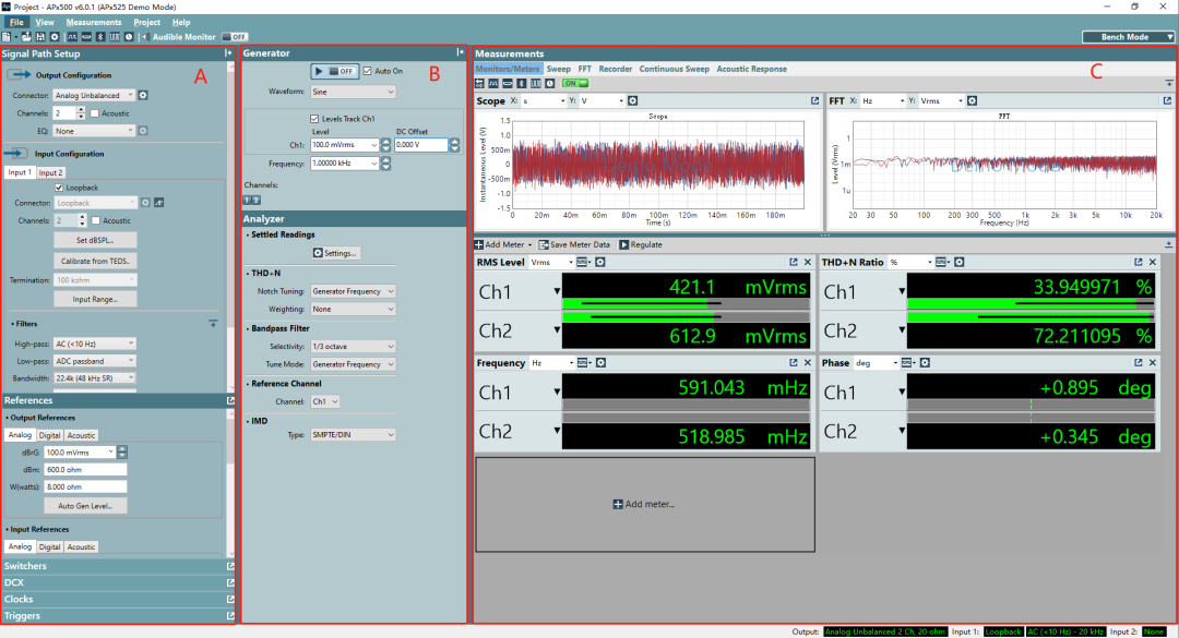
Figure 9 Bench mode interface
Area A: Input and output settings
Area B: Output signal settings
Area C: Test item settings and result display
Sequence Mode
Sequence Mode allows creation of a sequence of required test items and automatically runs the sequence, producing a test report.
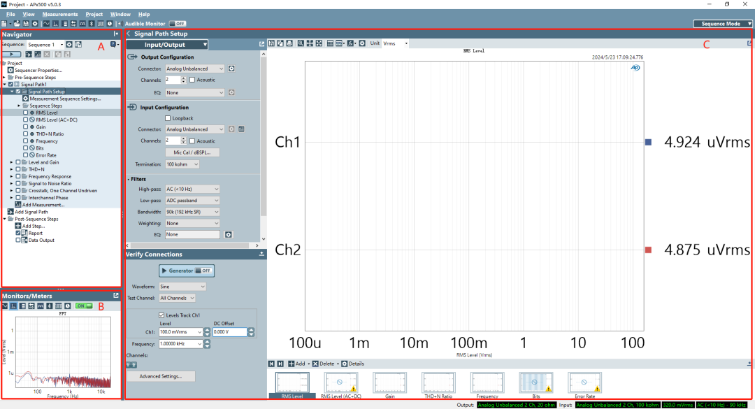
Figure 10 Sequence Mode interface
Area A: Test sequence and test item settings
Area B: Test monitoring window showing real-time time-domain and frequency-domain plots
Area C: Test item settings and result display
Below Area C, Input/Output related configuration information is shown.
Note: The Signal path setup test item is required and is used to configure the test input/output environment.
3. Sequence Mode Test Workflow
Sequence Mode is commonly used to generate audio test reports. The operation workflow is summarized below.
Step 1: Add measurements
Click "Add Measurement" to open a dialog and select the test items to add.
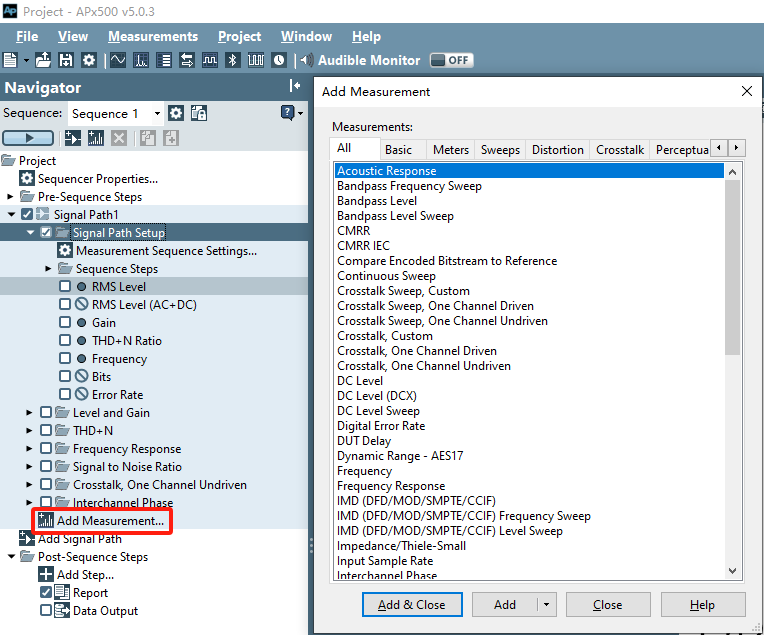
Figure 11 Add test measurement
Step 2: Adjust test order
Drag test items with the left mouse button to change their order. Click a test item to rename it.
Step 3: Select test items
From all added test items, check the ones required. Some test items contain multiple subitems; select subitems as needed.
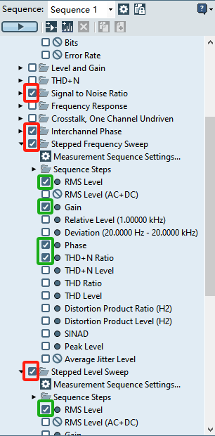
Figure 12 Select test items and subitems
Step 4: Configure test items
In Signal Path setup, configure the input and output forms according to actual needs.
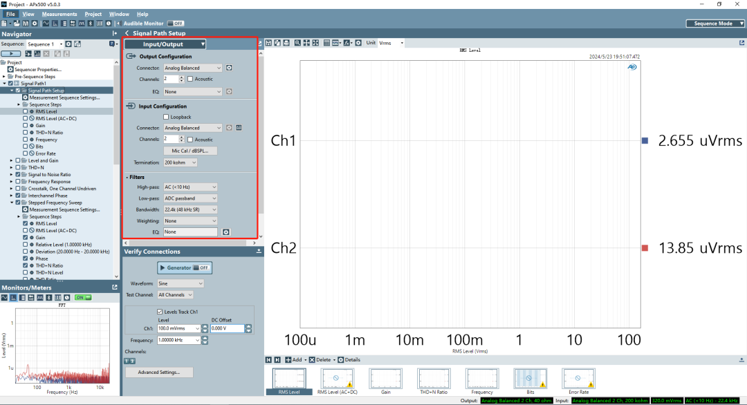
Figure 13 Input/output environment configuration
Configure test conditions for each test item and set the display format and units for results. After testing, the report will be generated according to these settings.
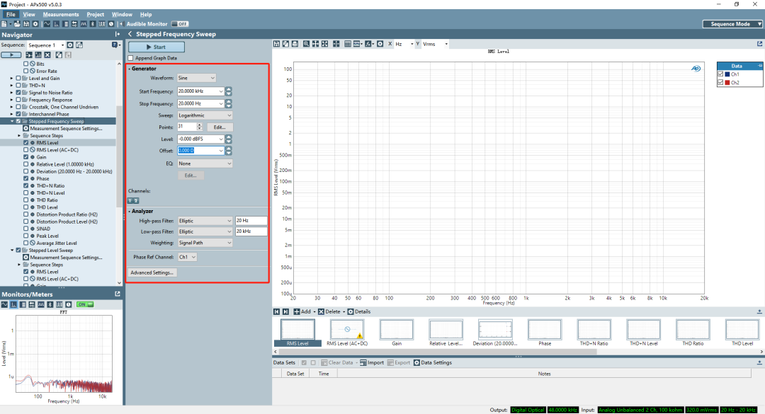
Figure 14 Configure subtest item conditions
Step 5: Run sequence and save report
Click the "Run Sequence" button to execute the tests.
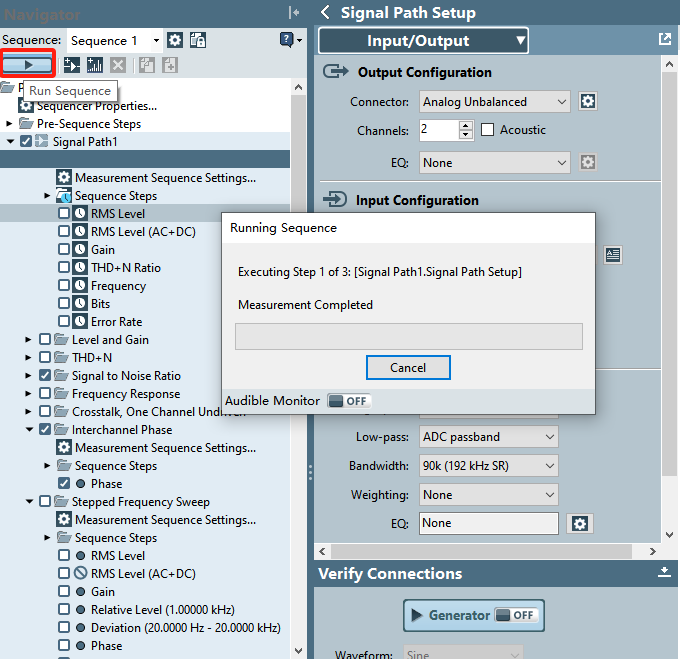
Figure 15 Run sequence
When the sequence completes, the Sequence report automatically appears. Confirm the report content and click "Export" to save the report.
Figure 16 Export test report
This chapter ends here. The next article will use the Telink TLSR9518A as an example to demonstrate testing methods for different input and output conditions.