Abstract
This article describes a portable human-machine interface (HMI) system based on the STM32 processor designed for total station measurement and calculation. The design uses software-simulated IO bus timing for the processor and an external SPI Flash to store the font library, reducing internal memory consumption by loading fonts from external Flash via SPI as needed. The hardware and software for a Chinese-character display system based on the ARM Cortex-M3 STM32F103RBT6 are presented, enabling a customizable Chinese font library for the HMI.
Background
When total stations are used for aircraft measurement, calculations are often required to meet diverse application scenarios and measurement requirements. Traditionally, these calculations are performed off-line on a computer using post-processing software. Modern surveying increasingly requires a portable handheld computation system to perform measurements in real time, and a Chinese-language HMI has become a de facto industry standard in many devices. A TFT LCD capable of displaying Chinese characters and a numeric keypad for input are essential elements for such handheld devices. Low power consumption is another core requirement for portable systems and must be considered in HMI design. This low-power HMI requires special consideration when selecting the processor and components; low power and high performance are primary selection criteria. This design uses STMicroelectronics' STM32F103RB based on the ARM Cortex-M3 core and a suitable LCD module to build a high-performance, low-power Chinese HMI system.
1. System Principle
The system is centered on the STM32F103RBT6 and uses an AM240320 TFT display as the LCD module to present the interface. Because the STM32F103RBT6 only has 128 KB of internal Flash, storing a Chinese font library internally would consume excessive on-chip resources. Therefore, the design stores the Chinese font library in an external SPI Flash and loads font glyphs into the processor via SPI when required. Since the STM32F103RBT6 does not provide an FSMC, the LCD module is driven using a software-simulated parallel bus timing.
2. Hardware Design
2.1 Power Supply Circuit
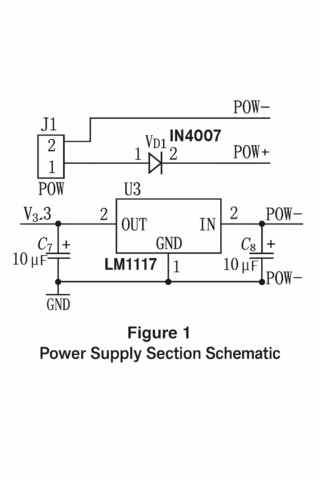
The system operates from a 3.3 V supply, so an external regulator is required. This design uses an LM1117-3.3 linear regulator to provide a stable 3.3 V supply for the processor, LCD, and SPI Flash. A diode IN4007 is placed in series on the positive supply rail to provide reverse-polarity protection. The power supply schematic is shown below.
2.2 LCD Display Circuit Design
The LCD display subsystem is driven by the microcontroller to present HMI states and characters by sending command words for module initialization and character rendering.
2.2.1 STM32F Series MCU Features
The STM32 family uses the ARM v7 Cortex-M3 core, which offers higher speed and lower power compared with earlier ARM7 cores, and integrates features such as branch prediction, single-cycle multiply, and hardware division to improve data-processing capability. The Thumb-2 instruction set reduces code density and improves execution efficiency. The STM32F103RBT6 selected here runs at 72 MHz and includes up to 128 KB of Flash and 20 KB of SRAM, along with rich enhanced I/O ports and peripherals connected to two APB buses. Its supply range is 2.0 to 3.6 V and multiple low-power modes support low-power applications, balancing performance and energy efficiency.
2.2.2 TFT LCD Module Characteristics
TFT LCDs are thin-film transistor displays where each pixel has its own semiconductor switch, allowing direct pulse control of each pixel, improved response speed, and precise control of color levels. Many ARM processors lack a dedicated LCD controller, and most Cortex-M3 microcontrollers do not include an integrated LCD controller. For systems without an LCD controller, common interfaces include Intel 8080 or Motorola 6800 parallel interfaces. This design uses STM32 GPIOs to emulate the 8080 interface timing to drive a 2.8-inch TFT. The selected AM240320 TFT module uses the ILI9320 main controller with an internal frame buffer of 240x320 and supports a 16-bit data bus in RGB565 format and multiple control interfaces including the 8080 parallel interface.
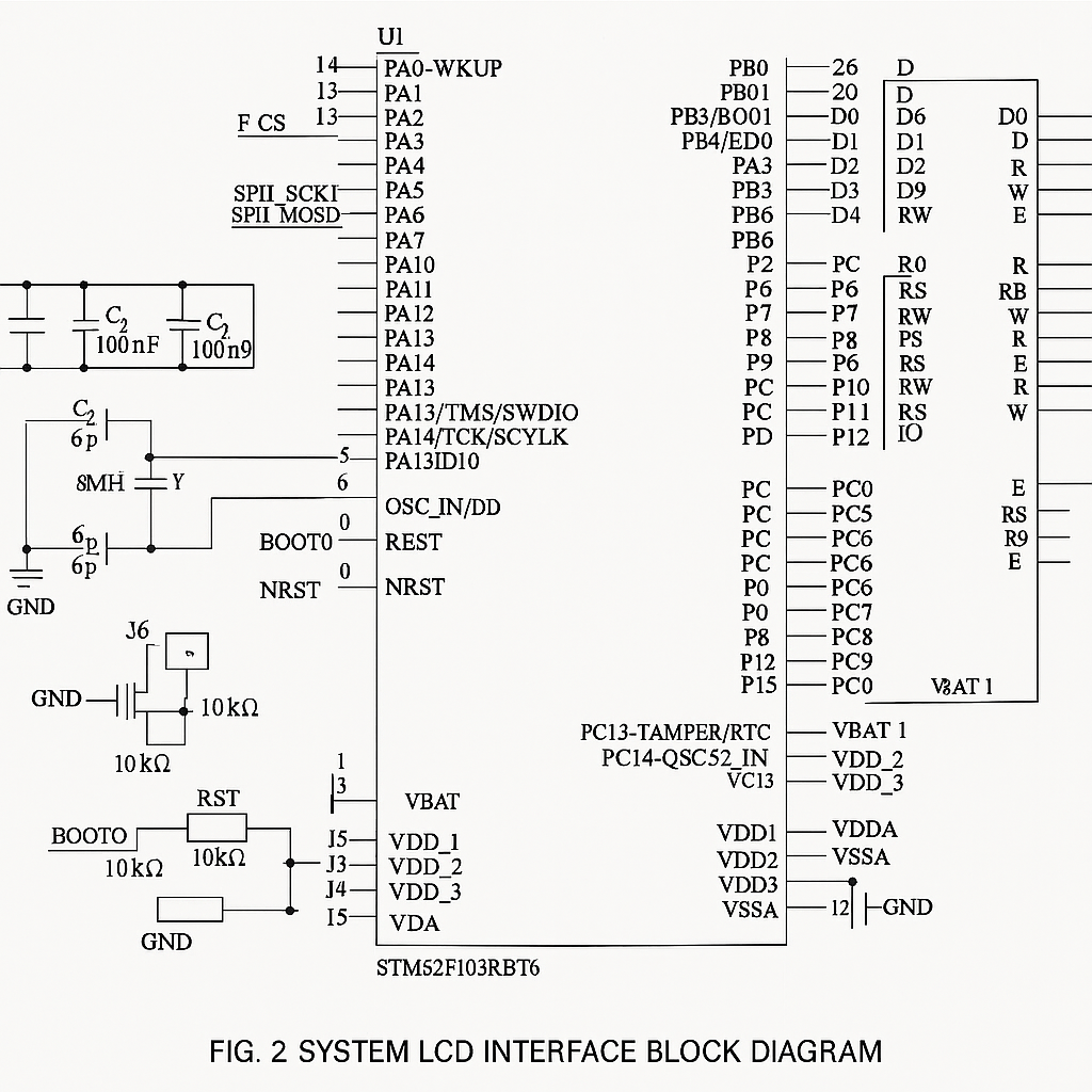
The STM32 uses an external 8 MHz crystal as the input clock and multiplies it via the internal PLL to 72 MHz system clock. The GPIO pins simulate 8080 timing to drive the 2.8-inch TFT. The processor-to-LCD hardware interface is shown below.
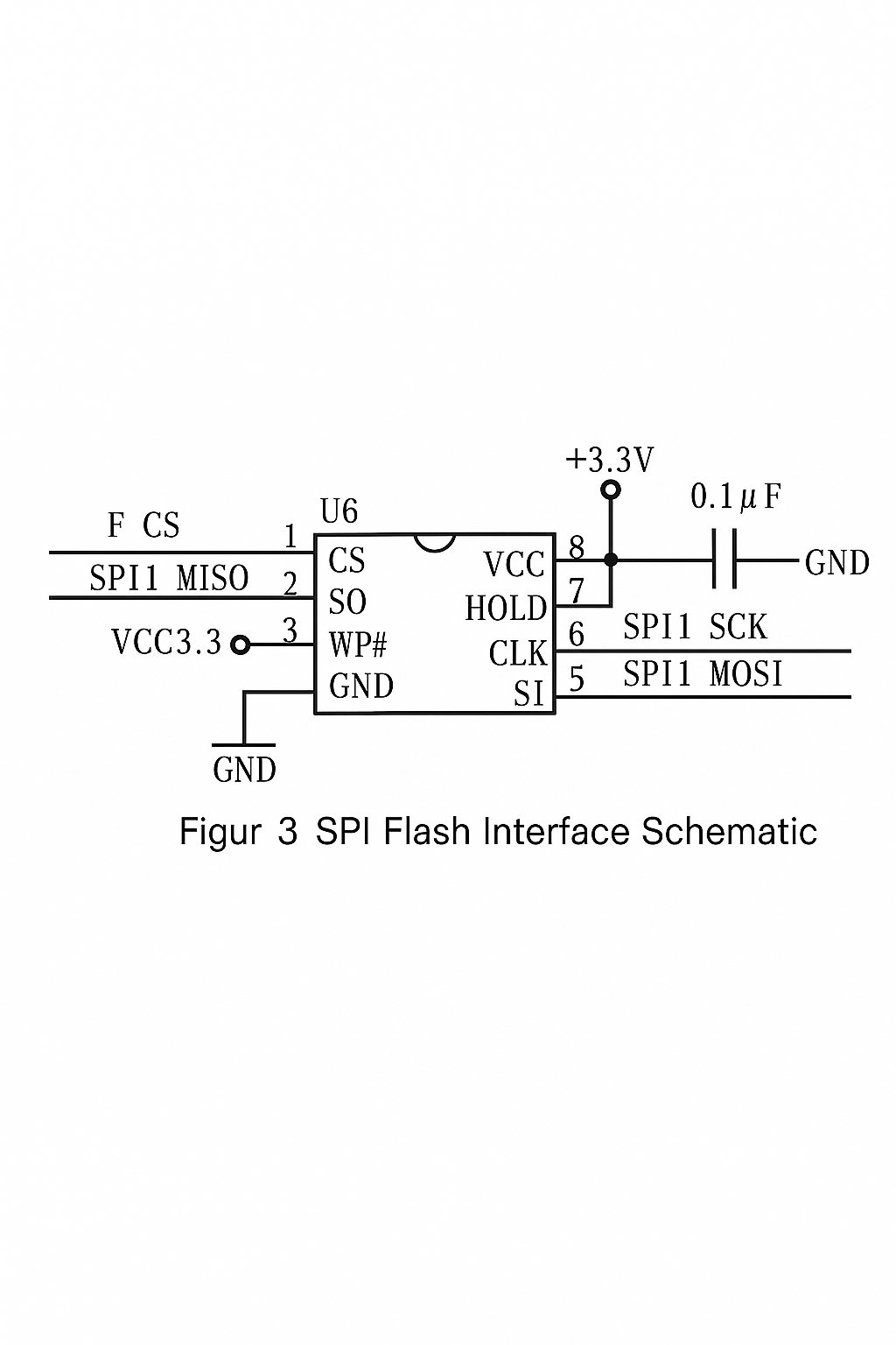
2.3 SPI Flash Font Storage Characteristics
The complete Chinese font library is stored in an external Flash chip, so the Flash selection must meet several requirements. First, it should use as few IO pins as possible because the TFT already consumes many parallel IOs; selecting a parallel-interface Flash would further increase IO usage, which is undesirable in a portable device. Therefore, this design uses an SPI Flash. SPI is a high-speed, full-duplex synchronous bus that uses only four lines on the chip package, saving pins and PCB space. This project uses the SST25VF080B from SST, an 8 Mbit SPI Flash with a 2.7 to 3.6 V operating range, supporting SPI mode 0 or mode 3 at up to 50 MHz. The smallest erase unit is a 4 KB sector, with 100k erase/write cycles and 100-year data retention. The STM32F103RBT6 includes a high-speed hardware SPI interface that easily connects to the SST25VF080B. The font storage hardware interface is shown below.