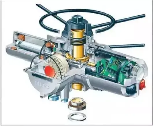
Overview
Inverter operating principle
Imagine you are a DC battery and someone asks you to produce AC power. How would you do it? If all the current you produce flows in one direction, what about adding a simple switch to the output lead? Rapidly opening and closing the current produces DC pulses, which at least accomplishes half the task. To generate proper alternating current, you need a switch that can fully reverse the current and do so about 50–60 times per second. Imagine flipping contacts back and forth more than 3,000 times per minute. That is the kind of mechanical action required.
In essence, old electromechanical inverters reduce to a switching unit connected to a power transformer. The transformer uses two coils, called primary and secondary, wound around a common iron core to convert low-voltage AC to high-voltage AC, or vice versa. In mechanical inverters, a motor or other automatic switching mechanism simply reverses contacts to flip the input DC across the primary winding, producing AC on the secondary, so the overall function is similar to a transformer-driven device. The switching mechanism works somewhat like the contact breaker in an electric doorbell. When powered, it magnetizes, pulls the contact open, then the spring returns the contact, repeating the cycle.
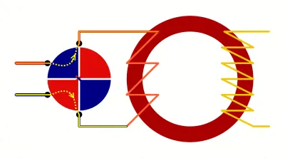
Animation: basic concept of an electromechanical inverter. DC flows through a rotating plate with cross-connected contacts (red and blue) into the primary winding of a toroidal transformer (brown donut). As the plate rotates, it repeatedly switches connections to the primary winding so the transformer receives alternating, rather than direct, input. This is a step-up transformer: the secondary winding (yellow zigzag) has more turns than the primary, so it raises the smaller AC input to a larger AC output. The disk rotation speed determines the AC output frequency. Most modern inverters do not operate this way; this example illustrates the concept. An inverter arranged this way produces a very coarse square-wave output.
Origins of the Inverter
In the late 1800s, US electrical pioneer Thomas Edison (1847–1931) vigorously promoted direct current (DC) as the preferred method for power distribution, while his competitor Nikola Tesla (1856–1943) advocated alternating current (AC). Despite Edison's efforts, AC systems prevailed and modern power distribution has largely been based on AC ever since. Many small prime movers and generators, however, produce DC. This created a need to convert DC from sources such as vehicle batteries into AC for appliances, which is where inverters became necessary.
Difference Between DC and AC
When teachers explain basic electricity concepts, they often describe direct current. In DC, electrons move in one direction, similar to an ant trail carrying leaf pieces. A flashlight circuit, for example, contains a battery, bulb, and switch; current flows from the battery to the lamp until the battery is depleted. Household power from a wall outlet, however, is based on alternating current, where the current reverses direction about 50–60 times per second (50–60 Hz). It can seem puzzling how AC transmits power when electrons only oscillate back and forth a short distance instead of traveling to the lamp and back. The key is that when you turn on a lamp, the rapid oscillation of electrons in the conductor drives energy into the filament as heat, producing light. Electrons in AC do not need to flow in a loop to transfer energy; they oscillate in place.
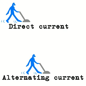
Animation: the difference between direct current and alternating current. If vacuuming a room, DC is like moving in a straight line from one side to the other, while AC is like working back and forth in place. Both accomplish work, but in different ways.
What Is an Inverter?
Most household appliances are designed to use AC power. Devices that require DC but must be powered from an AC outlet use a rectifier to convert AC to DC. An inverter performs the opposite function, converting DC into AC.
If a flashlight battery supplies DC and you reverse the battery, the lamp still lights but the current direction is reversed. If a person could flip the battery 50–60 times per second, that person would act as a mechanical inverter, producing AC at the desired frequency. Some inverters use high-speed electromagnetic switches to reverse current direction; these mechanical designs typically generate a square-wave output where current is either in one direction or the opposite, switching instantly between the two:

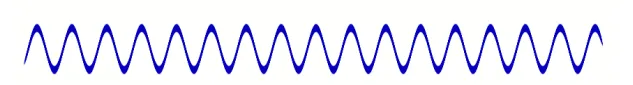
Such abrupt reversals can be harsh for some electrical devices. In conventional AC mains, current transitions gradually in a sinusoidal pattern, as shown below:
Electronic inverters can produce a smoothly varying AC output that approximates a sine wave. They use inductors and capacitors to shape the output so it rises and falls more gradually than the abrupt on/off square wave. Inverters can also be used with transformers to change a DC input voltage into a different AC output voltage, higher or lower. Output power, however, must always be less than input power due to losses when current flows through electrical and electronic components; some energy is inevitably dissipated as heat. Practical inverters typically achieve efficiencies above 90%. A range of inverters is available for use with renewable energy sources such as solar panels and small wind turbines.