Permanent magnet synchronous motors (PMSMs) power demanding industrial control systems and electric vehicle drives, where motor performance directly depends on the supporting power electronics and control PCBs. Effective PCB design must address electromagnetic excitation, thermal loads, high-frequency switching, signal integrity, and mechanical integration to achieve reliable operation, high efficiency, and long service life. Aivon's expertise in multilayer PCB fabrication, material selection, and high-density interconnect (HDI) processes supports these requirements by enabling optimized layouts that mitigate vibration-induced failures, manage heat from motor drives, and maintain signal fidelity in compact, high-speed environments.
Electromagnetic Excitation and PCB Vibration Mitigation
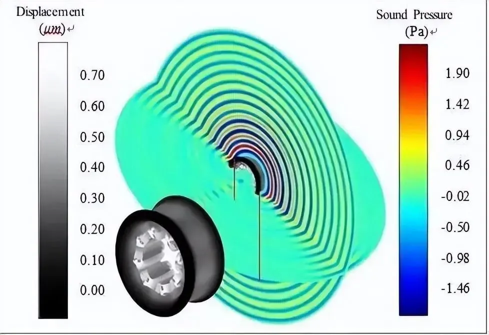
Vibration and noise in PMSMs originate primarily from electromagnetic forces acting on the stator core, aerodynamic effects, and mechanical imbalances. Radial electromagnetic forces induce stator deformation that transmits through the housing, while tangential components contribute to cogging torque ripple. In propulsion and industrial applications, electromagnetic excitation dominates.
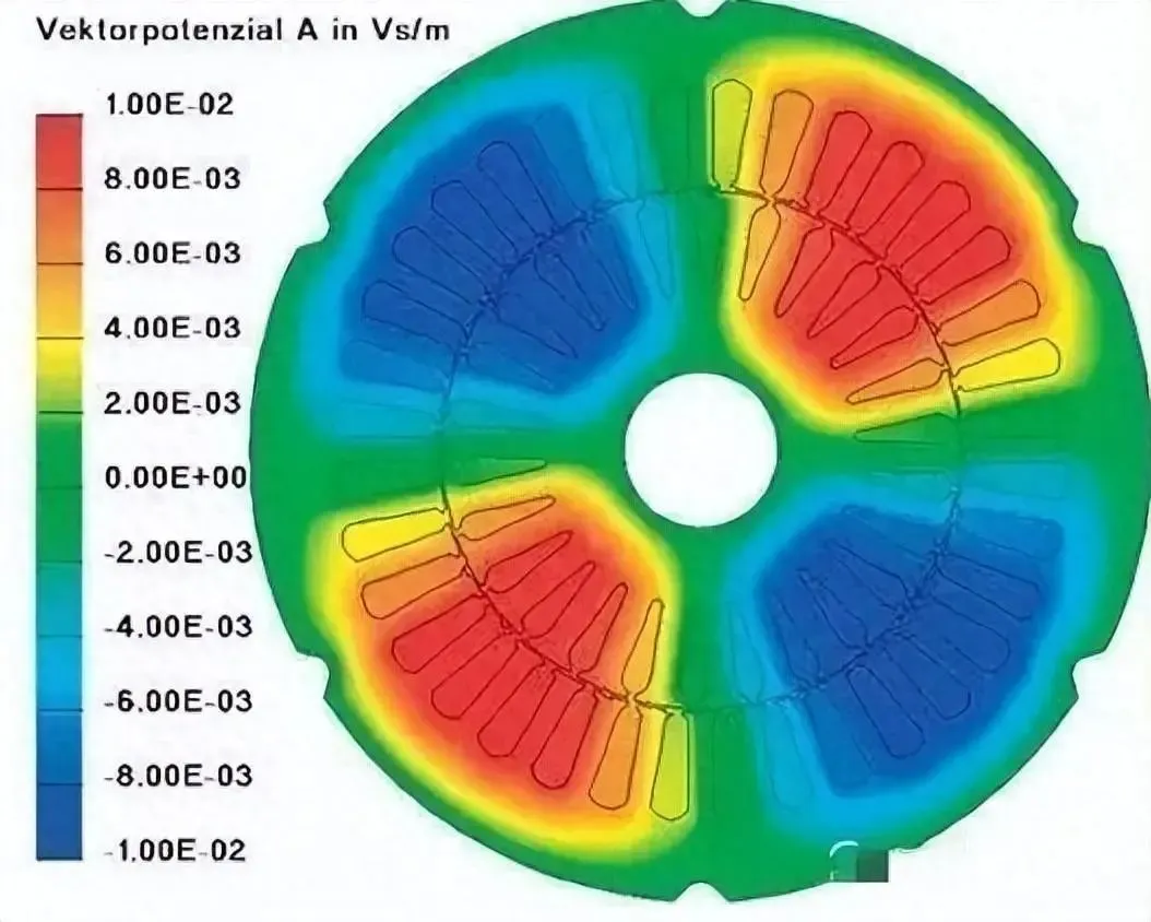
These forces create mechanical stress that can propagate to mounted PCBs, causing micro-cracks in traces, solder joint fatigue, or resonance in sensitive components. PCB designers address this through strategic component placement away from high-vibration zones, use of flexible substrates or damping materials in stack-ups, and reinforced mounting pads. Finite element analysis during the PCB layout phase helps predict resonance frequencies and guides the selection of high-Tg laminates or reinforced cores to maintain structural integrity under continuous electromagnetic loading.
Early modeling of motor vibration response informs PCB stack-up decisions, such as increased copper thickness for mechanical robustness or symmetric layer arrangements to reduce warpage under thermal cycling induced by motor operation.
Magnetic Circuit Configurations and Control Electronics Implications
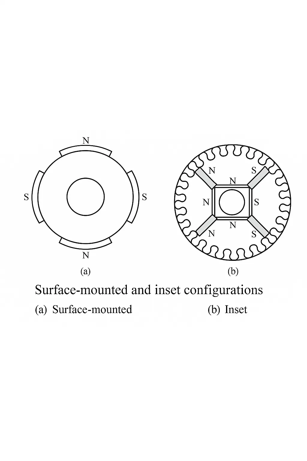
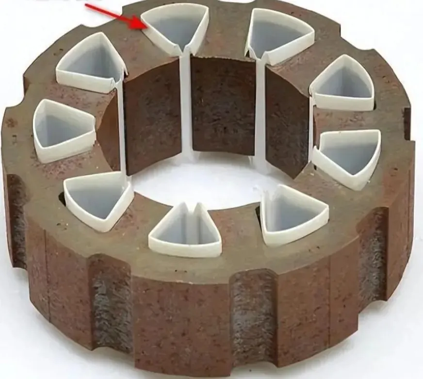
Permanent-magnet motor magnetic circuits vary by magnet location (rotating-pole vs. rotating-armature), material type (single vs. ), placement (surface-mounted vs. interior-mounted), and shape (segmental, arc, rectangular, claw-pole). Surface-mounted designs simplify assembly but expose magnets to stronger armature reaction, while interior-mounted configurations provide higher flux density at the cost of increased leakage and manufacturing complexity.
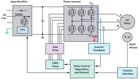
These choices influence back-EMF waveforms, inductance characteristics, and torque ripple, directly affecting the inverter and controller PCBs. Interior PM motors often require more sophisticated field-oriented control algorithms implemented on high-performance microcontrollers or DSPs mounted on the PCB. PCB layouts must accommodate precise current sensing and PWM generation while managing the resulting electromagnetic interference (EMI) through careful grounding schemes, shielding layers, and optimized trace routing to preserve signal integrity.
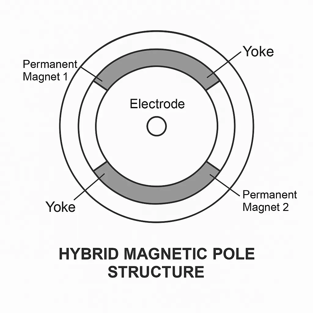
Hybrid magnet structures can reduce costs but introduce flux variations that demand tighter tolerances in PCB-based current and voltage feedback loops. Material selection for the PCB—such as low-loss dielectrics—helps maintain performance when motors operate across wide speed ranges.
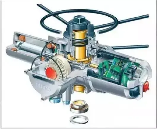
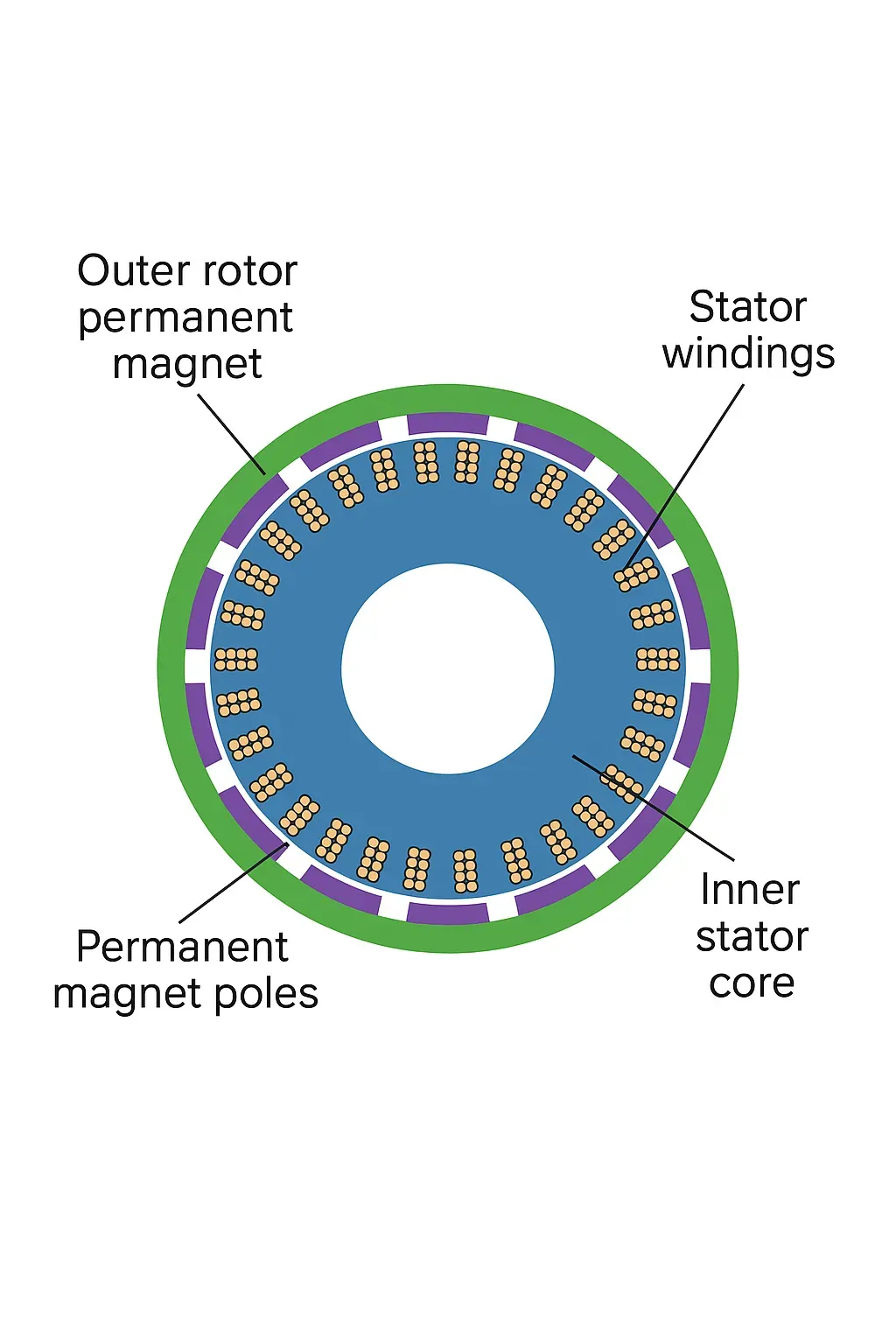
Rotor Architectures: Inner vs. Outer and PCB Integration Challenges
Inner-rotor PMSMs typically achieve higher speeds with larger magnet volumes, suiting high-speed industrial machinery. Outer-rotor designs offer compact axial length, lower magnet volume in some cases, and better suitability for direct-drive applications with integrated cooling.
Outer-rotor configurations often place the stator closer to the system housing, influencing PCB mounting locations and thermal paths. Compact outer-rotor motors in small-form applications require densely populated PCBs with minimal footprint. High-speed inner-rotor motors generate stronger electromagnetic fields that necessitate enhanced EMI shielding on the PCB, including dedicated ground planes and via stitching.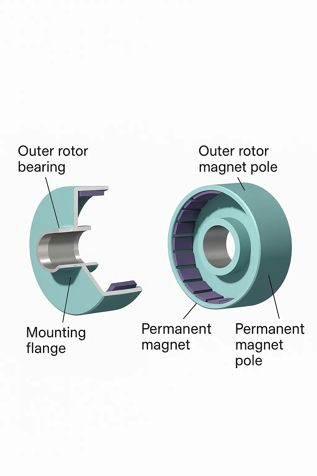
Designers must also consider the center-of-gravity effects and dynamic balancing requirements, which can translate into PCB-level mechanical reinforcements or isolated mounting strategies to prevent vibration transmission to sensitive analog circuits.
Winding Technologies and Power Electronics Optimization
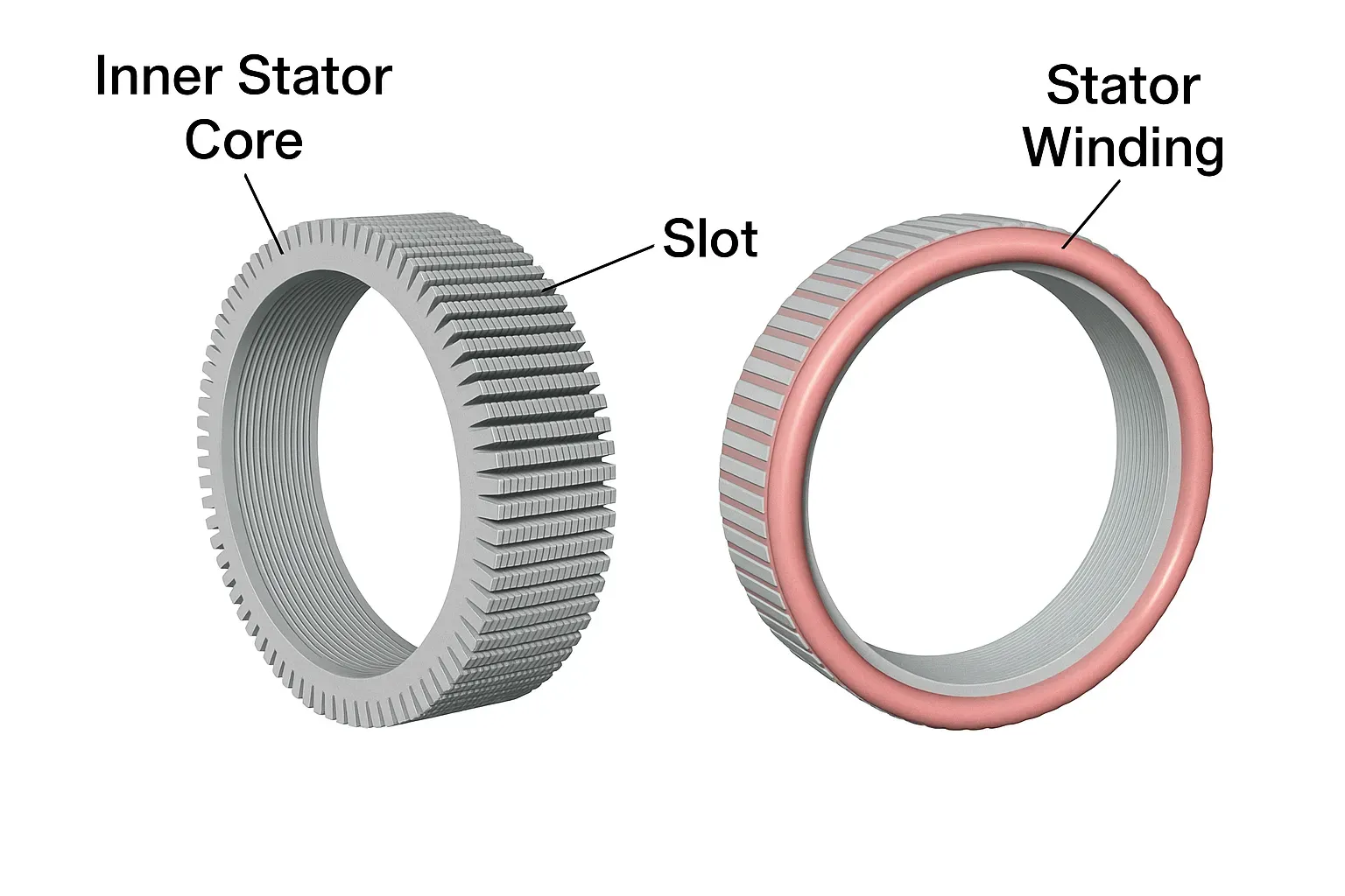
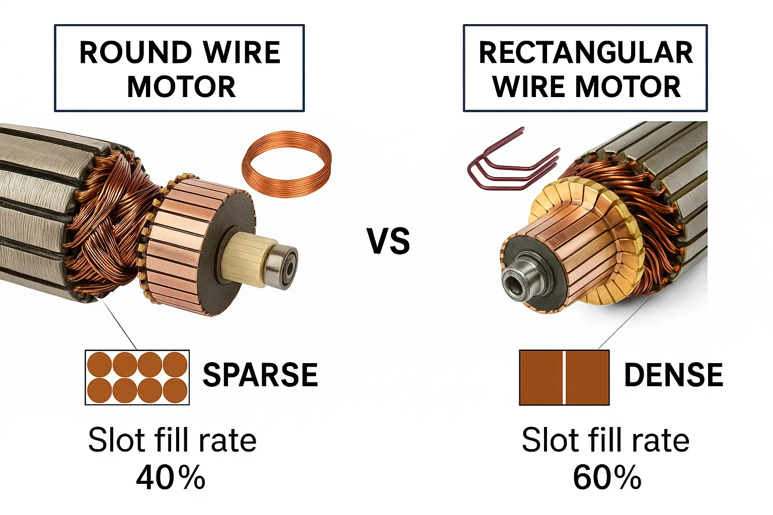
Slot fill ratio directly impacts motor efficiency and copper losses. Practical factors such as insulation thickness, enamelled wire diameter, and required clearances often reduce achievable fill to 30–50% in conventional windings. Flat-wire (rectangular conductor) windings significantly improve slot fill, reduce AC losses, enhance thermal performance, and lower noise compared with round-wire designs.
In automotive 800V platforms, hairpin, I-pin, and continuous wave flat-wire configurations enable higher power density. Hairpin windings balance efficiency and manufacturability but require precise end-winding management. These higher-efficiency motors reduce overall system losses, allowing PCB-based inverters to operate with lower current ratings or smaller form factors while still delivering required torque.
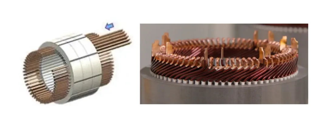
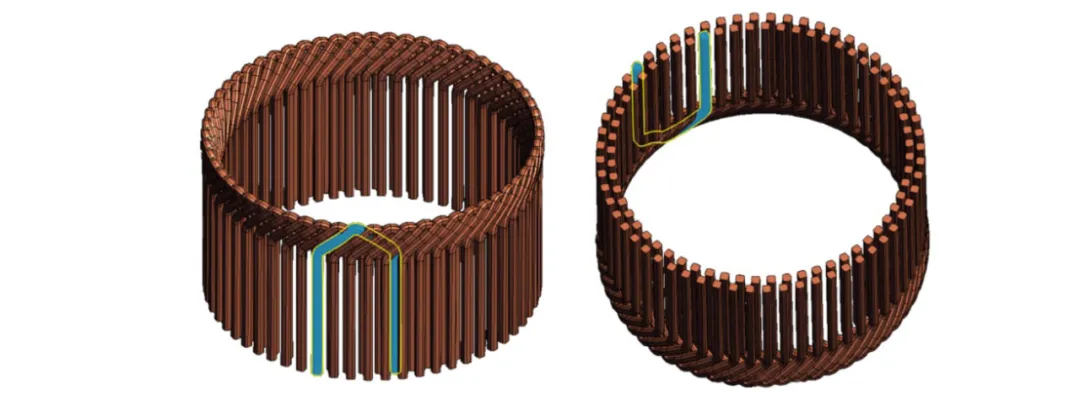
PCB implications include support for higher switching frequencies enabled by reduced motor losses, demanding low-inductance layouts, optimized gate driver placement, and power planes with sufficient copper weight. Transposition techniques in advanced flat-wire designs further minimize circulating currents, easing requirements on PCB current-sensing accuracy.
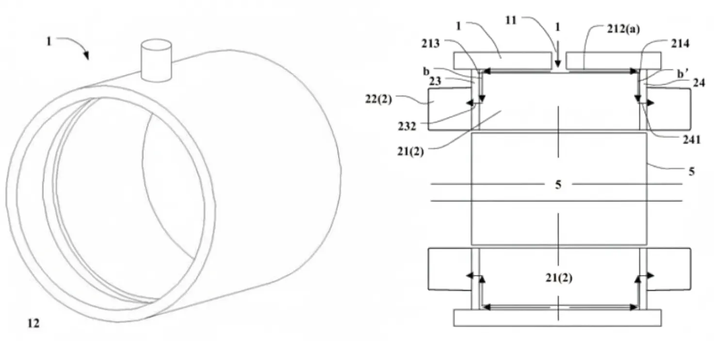
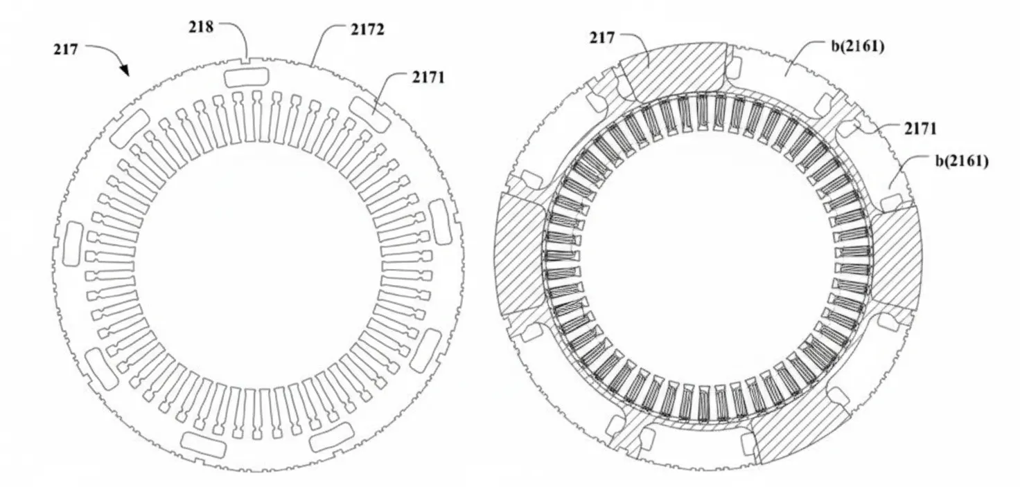
Cooling Strategies and PCB Thermal Management
Oil cooling has emerged as a preferred method for high-power-density PMSMs, providing direct cooling of stator windings and rotor components while offering lubrication benefits. Patented designs incorporate axial and radial channels within the stator core, spray mechanisms at winding ends, and specialized lamination stacking to achieve uniform coolant distribution.
Effective motor cooling reduces the thermal burden on adjacent drive electronics. PCB thermal design must still account for residual heat from power semiconductors and high-frequency losses. Techniques such as thermal vias, metal-core PCBs, embedded copper coins, and strategic component spacing become critical. High-Tg materials and optimized stack-ups prevent delamination under the combined thermal cycling from motor operation and power dissipation.
Integrated oil-temperature sensing in multi-in-one motor systems further requires precise analog PCB circuits with low-noise layouts and appropriate sensor placement.
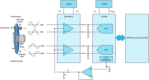
Position Sensing in High-Speed, Compact Applications
Accurate rotor position feedback is essential for vector control, field-weakening operation, and MTPA strategies across the full speed range. Optical encoders generate high-resolution sine/cosine signals that require synchronized, high-speed analog-to-digital conversion on the PCB.
In small-form, high-speed applications, PCB real estate constraints favor highly integrated solutions: dual-channel differential ADCs, low-noise amplifiers, and compact packages that support oversampling for enhanced resolution without increasing encoder disc complexity. Differential signaling, impedance-controlled traces, and careful reference voltage routing preserve signal integrity amid motor-generated noise.
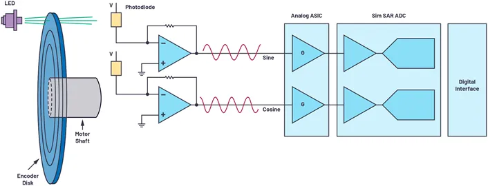
PCB designers must balance sampling rates (often several MSPS) with power consumption and board space, using techniques such as on-chip oversampling and reduced data rates to simplify digital interfaces to the motor controller ASIC or MCU.
Future Trends in PCB Design for Next-Generation PMSM Systems
Emerging technologies are reshaping PCB requirements for PMSM applications. Wide-bandgap semiconductors such as SiC and GaN enable switching frequencies above 100 kHz, demanding ultra-low-inductance layouts, advanced substrate materials with superior thermal conductivity, and enhanced isolation distances to withstand steeper voltage slopes.
HDI and rigid-flex PCBs are increasingly adopted for integrated motor-drive modules, allowing three-dimensional component placement that reduces parasitic inductance while fitting within tight motor housings. Embedded passive components and sensors further miniaturize control electronics and improve reliability by eliminating external interconnects prone to vibration damage.
Sustainability initiatives drive the adoption of halogen-free, recyclable laminates and low-loss dielectrics that maintain performance under high-temperature operation. Digital twin simulations and AI-assisted layout optimization are becoming standard, enabling predictive analysis of thermal, mechanical, and electromagnetic behavior before fabrication.
Multi-in-one systems combining motor, inverter, and gearbox place additional emphasis on high-voltage isolation, creepage/clearance management, and thermal interface materials within the PCB stack-up. These trends collectively push PCB manufacturers toward tighter process controls, finer feature sizes, and advanced surface finishes to support the next wave of high-efficiency, compact PMSM deployments.
Conclusion
PCB design and manufacturing are integral to unlocking the full performance, reliability, and efficiency of modern permanent magnet synchronous motors. From mitigating electromagnetic vibration and optimizing thermal paths to ensuring signal integrity in position feedback and power stages, every aspect of the PCB directly influences system-level outcomes in industrial control and automotive applications.
By applying rigorous material selection, stack-up engineering, EMI mitigation, and manufacturing precision, designers can address the unique challenges posed by advanced windings, cooling methods, and high-speed operation. As motor technologies continue to evolve, close collaboration between motor engineers and PCB specialists remains essential for delivering robust, high-density solutions that meet stringent reliability and performance standards.