Overview
This document describes S7-1200 PWM configuration and programming methods. The example uses a DC/DC type S7-1200 CPU. Insert the S7-1200 CPU (DC output type) into the project in Portal software and configure PWM in the Device view.
Hardware and Software
Hardware:
- S7-1200 CPU (example uses V4.4 S7-1215C DC/DC/DC)
- PC with Ethernet card
- TP cable (Ethernet cable)
Software:
- STEP7 V11 or later (example uses V16)
Related Reading: Overview of PLC Ethernet Open Communication
Hardware Configuration
1. Open the CPU General properties and set the pulse generator.
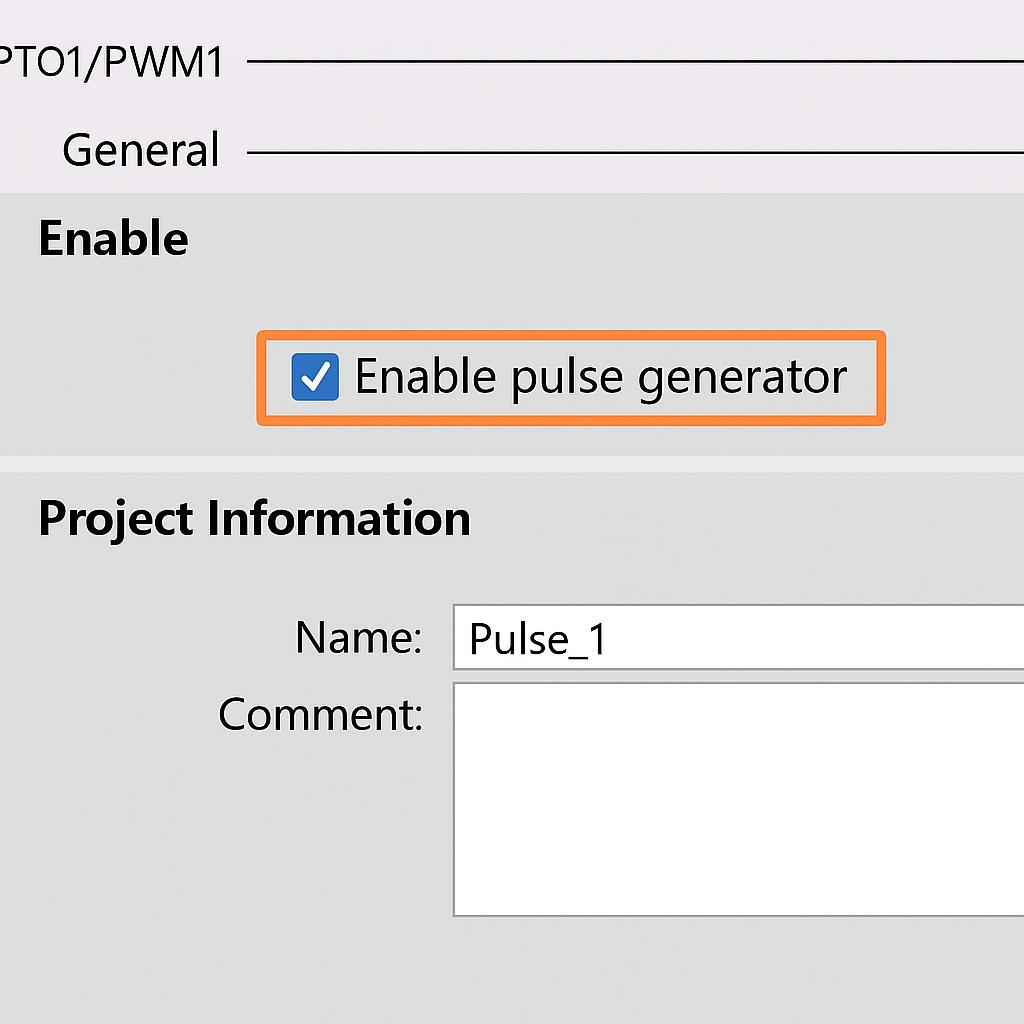
2. Enable the pulse generator. You may assign a name or use the default settings. You can also add comments for the PWM pulse generator. See Figure 1.1.
3. Parameter assignment: configure the pulse parameters. The Parameter assignment section defines the period unit and pulse width for the PWM pulse. See Figure 1.2.
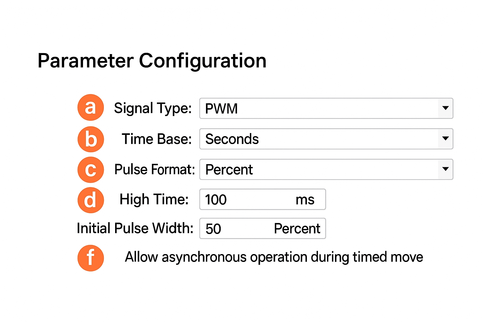
a. Signal type: select the pulse signal type. There are PWM and PTO options. Choose PWM in this example. See Figure 1.3.
b. Time base: sets the time unit for the PWM period. In PWM mode, the time base unit can be milliseconds or microseconds.
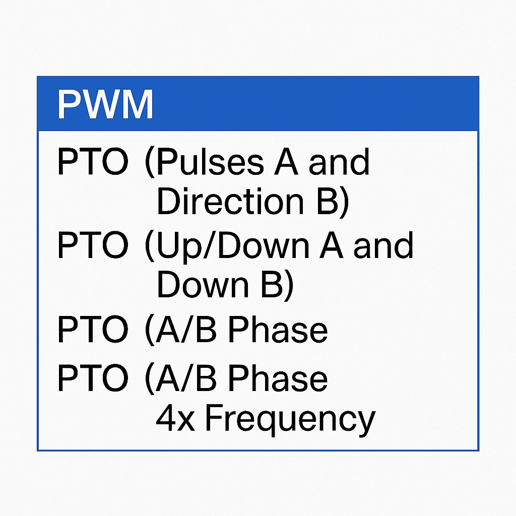
c. Pulse width format: defines the resolution of the PWM duty cycle. There are four options; see Figure 1.4.
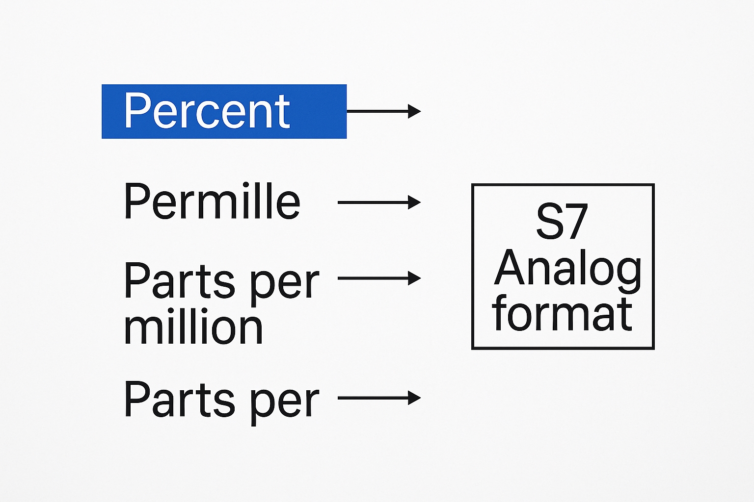
For example, the "percent of 100" option divides the PWM period into 100 steps; each step represents 1/100 of the period. "Per mille" and "per ten thousand" provide finer resolution. The "S7 analog format" divides the period into 27648 steps, corresponding to the S7-1200 analog range 0..27648 or -27648..27648.
d. Cycle time (PWM only): specifies the PWM period. Portal limits the range to 1..16777215. If the "Allow modifying cycle time at runtime" checkbox is selected, the cycle time can be changed while running.
e. Initial pulse width (PWM only): sets the initial high-level pulse width within the period. The allowed range depends on the chosen pulse width format. For example, with the "per ten thousand" format the range is 0..10000; with "S7 analog format" it is 0..27648. The initial pulse duration can be changed at runtime via the configured Q output address.
f. Allow modifying cycle time at runtime (PWM only): if selected, the CPU allocates 4 additional Q bytes for the cycle time. The cycle time can then be modified while the program is running.
4. Hardware output: select a DO point on the S7-1200 PLC to use as the PWM output. See Figure 1.5.
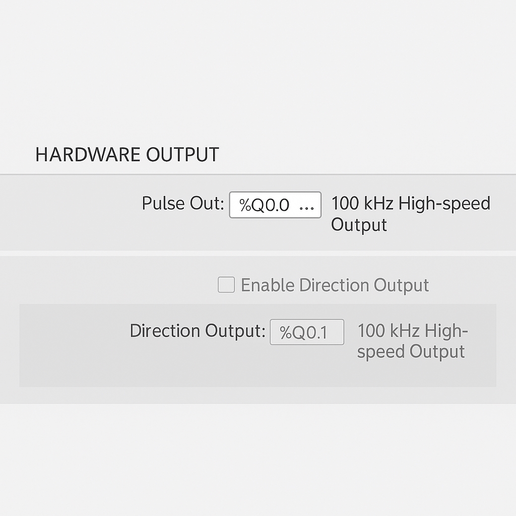
Note: The selected output must be a DO point on the CPU or a DO point on the SB signal board. DO points on S7-1200 SM expansion modules do not support PWM.
5. I/O address: set the PWM address and the method for updating the cycle. See Figure 1.6.
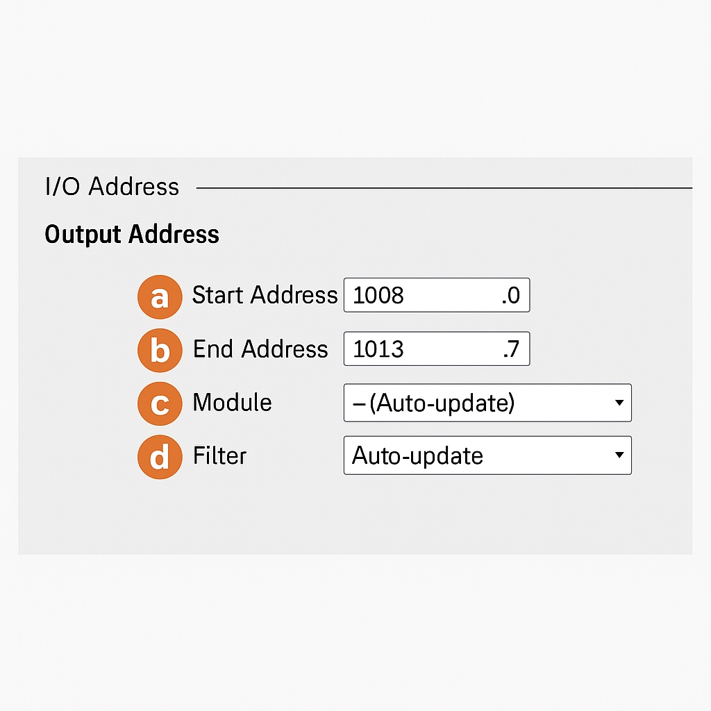
a. Start address: sets the PWM channel address.
b. End address: determined by the start address. By default, each PWM channel uses one word for the pulse duration output. If the "Allow modifying cycle time at runtime" option is enabled, the CPU allocates 6 output bytes: the first 2 bytes for pulse duration and the next 4 bytes for cycle time.
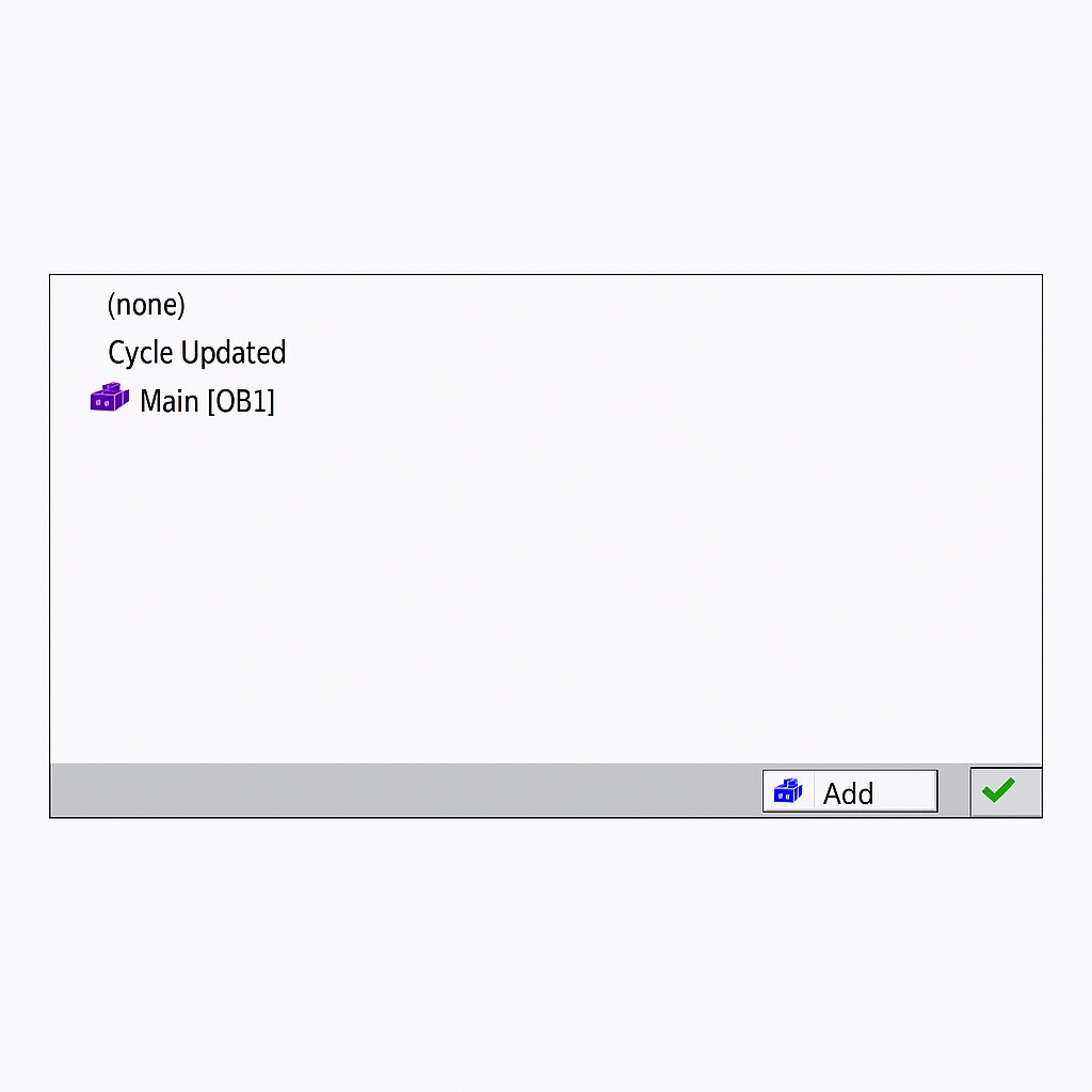
c. Organization block: sets which OB block the PWM I/O address updates are based on. You can add OBs as needed. In this example, the default "Automatic update" option is used. See Figure 1.7.
d. Process image: configures how the PWM I/O addresses are updated in the process image. The PWM I/O address refers to the address that stores the pulse width value. See Figure 1.8.
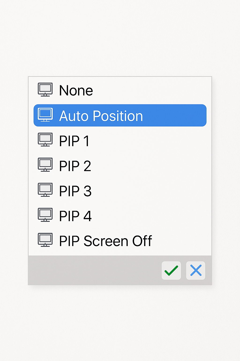
The S7-1200 provides six process image partitions. The first partition "Automatic update" is used for I/O that should be updated every scan cycle; this is the default. Partitions PIP1..PIP4 can be assigned to different interrupt events. If an I/O is assigned to a PIP partition but no OB is assigned to that partition, the CPU will not update that I/O via the process image. For immediate access to physical I/O without using the process image, append the suffix ":P" to the address.
Based on the above, this example uses "Automatic update". Since the PWM I/O addresses are outputs (Q), you can use QWx/QDx, or direct physical access QWx:P/QDx:P.
Software Programming
1. Open program blocks in Portal and insert the CTRL_PWM instruction. The instruction is located under Extended Instructions - Pulse. Drag or double-click CTRL_PWM to add it to the program.
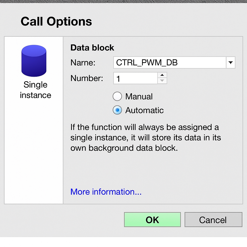
2. When inserting CTRL_PWM, you will be prompted to associate a background data block. The name and number can be set manually or left as the system default. See Figure 2.1.
3. Configure the CTRL_PWM instruction parameters. See Figure 2.2 for pin mapping.
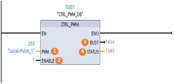
Key parameters:
- PWM: hardware ID of the pulse generator. This is the hardware identifier; in the example it is 265.
- ENABLE: PWM enable input. When TRUE the CPU outputs PWM; when FALSE no pulse is output.
- BUSY: indicates whether the CPU is currently outputting a PWM pulse.
- STATUS: status value of the PWM instruction. STATUS=0 indicates no error; nonzero values indicate errors. Refer to help or manuals for error codes.
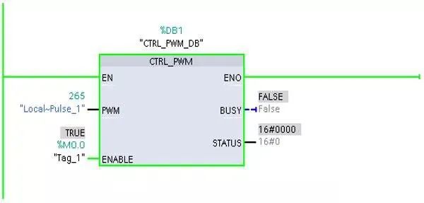
4. Monitor the program and modify PWM pulse width and cycle time online. In this example, use M0.0 to enable the CTRL_PWM instruction. See Figure 2.3.
To modify the PWM pulse width at runtime, change the QWx value, where x corresponds to the configured PWM output I/O address.
To modify the PWM cycle time at runtime, first enable "Allow modifying cycle time at runtime" in hardware configuration, then modify QD(x+2).
For example, after enabling that option the CPU allocates six bytes for PWM1, e.g., QB1008..QB1013. After downloading and starting the program, use QW1008 to modify the pulse duration and QD1010 to modify the cycle time.
To monitor these values, add a new watch table from the project tree Monitoring and Force Tables. In the watch table enter addresses QW1008 and QD1010 in the Address column and set Display format to Signed Decimal. Click the Monitor button to view the values. Figure 2.6 shows QW1008=50 and QD1010=100, corresponding to the configured initial pulse width and cycle time.
Perform testing and experiments as needed.
Relateed Reading: PLC Installation and Commissioning Procedure
Common Questions
Question 1: How to change the PWM pulse width?
Answer: Set the PWM I/O address. In the example, modify QW1008 to change the PWM pulse width in real time.
Question 2: How to change the PWM cycle time?
Answer: Enable "Allow modifying cycle time at runtime" in hardware configuration, then modify the corresponding QD address. In the example, modify QD1010 to change the PWM cycle time in real time.
Question 3: What is the minimum pulse duration for PWM output?
Answer: If the time base is milliseconds, the actual pulse width must be greater than or equal to 1 millisecond. If the time base is microseconds, the actual pulse width must be greater than or equal to 1 microsecond. If the pulse width is less than one time-base unit, the output will be turned off. For example, with a cycle time of 10 microseconds, a 5% duty cycle produces a 0.5 microsecond pulse width. Since that is less than 1 microsecond, the PWM output will be off.