Programmable Logic Controllers (PLCs) form the backbone of modern industrial automation, handling everything from motor control and sequential processes to PWM signaling and fault monitoring. The performance, reliability, and longevity of any PLC system depend heavily on the underlying printed circuit boards (PCBs) that host I/O modules, power supplies, communication interfaces, and processing units.
At Aivon, we specialize in manufacturing high-reliability PCBs tailored for industrial environments, where factors like signal integrity, thermal management, EMI/EMC compliance, and long-term durability directly impact system uptime and safety.
From Traditional Schematics to PCB-Integrated PLC Control
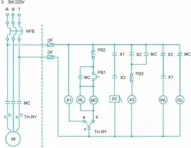
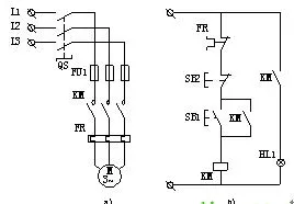
Traditional electrical schematics for three-phase motor control—complete with contactors, thermal relays, push buttons, and indicator lamps—represent hardwired relay logic. Converting these to PLC ladder diagrams replaces physical wiring with software, but the transition requires careful PCB-level implementation.
Key considerations during this conversion include:
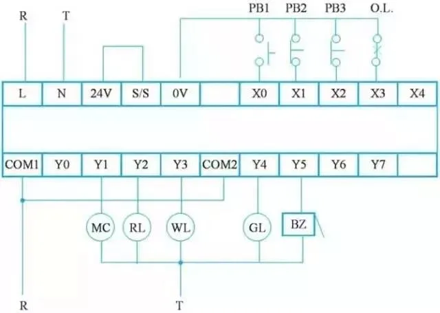
- I/O assignment and wiring methods: Inputs and outputs must map precisely to PLC terminals. On the PCB, this translates to optimized trace routing, proper connector placement, and selection of normally open (NO) or normally closed (NC) configurations to ensure reliable signal transmission.
- Contact and coil placement: Ladder logic requires contacts before coils. PCB designers must account for this by ensuring clean signal paths that minimize crosstalk and maintain isolation between high-voltage power circuits and low-voltage control signals.
- External wiring diagrams: These map directly to PCB edge connectors, terminal blocks, and isolation barriers. High-quality multilayer PCBs with appropriate copper weights and dielectric materials prevent voltage drops and support the NPN/PNP wiring schemes common in industrial setups.
By designing PCBs with these conversions in mind, engineers achieve cleaner layouts that support both the original relay logic and modern software-based control.
Practical Programming Considerations Reframed for PCB Performance
Effective PLC programming tips—such as control mode flags, analog filtering, sequential stepping with +10 increments, fault latching, reusable subroutines, overcycle protection, NC safety inputs, and actuator behavior principles—rely on stable hardware foundations.
- Analog signal integrity: Noisy analog inputs demand robust PCB design, including proper grounding planes, shielding traces, and filtering components. High-Tg FR4 materials and controlled impedance routing help maintain signal accuracy in electrically noisy industrial settings.
- Sequential control and timing: Timers and step-tracking logic perform best when supported by low-jitter clock signals and stable power delivery on the PCB. Copper thickness and thermal vias ensure consistent performance under varying loads.
- Safety and fault handling: NC wiring for emergency stops and limit switches benefits from PCBs with reinforced isolation, creepage and clearance distances, and redundant paths to prevent single-point failures.
- Output management and efficiency: Outputs that activate only when needed reduce heat generation. PCB thermal management—through optimized copper pours, heatsinks, and material selection—extends component life and prevents thermal runaway in continuous-operation machines.
These software practices achieve their full potential only when paired with PCBs engineered for industrial reliability.
Advanced PLC Features and PCB Implementation
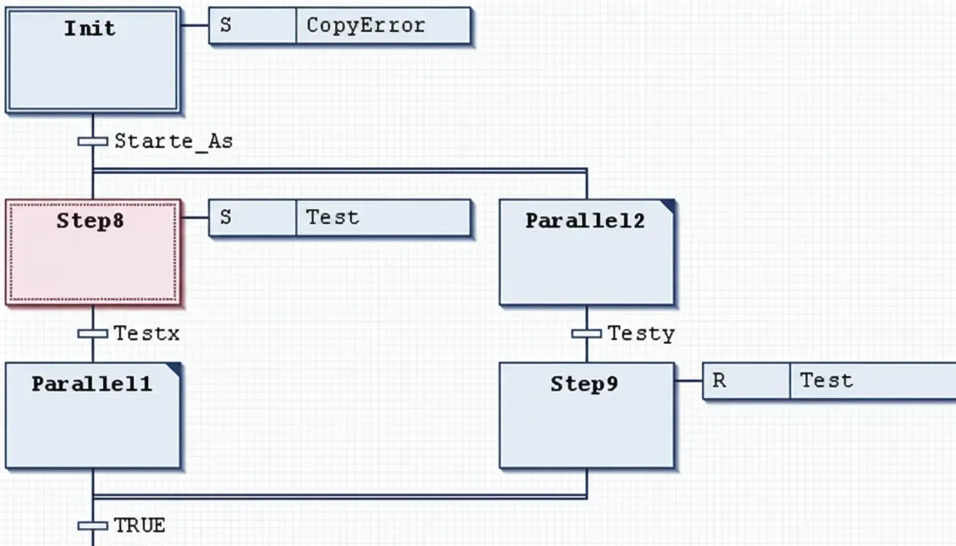
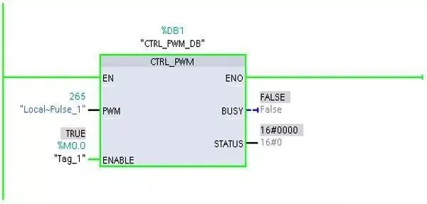
Techniques like Sequential Function Chart (SFC) programming, PWM configuration on platforms such as the S7-1200, and handling of number systems (including BCD conversion) introduce additional hardware demands.
- SFC and modular design: Parallel branches and handshake mechanisms between subroutines require PCBs with high-density interconnects (HDI) for complex routing, along with dedicated power and ground planes to support multiple simultaneous processes without interference.
- PWM signal generation: Precise pulse-width modulation for motor speed control or actuators demands tight control over trace impedance, minimal parasitic inductance, and clean power delivery. PCBs supporting high-frequency PWM benefit from low-loss dielectrics and careful via placement to preserve signal fidelity.
- Data handling and conversions: Number system conversions and signal type calculations (analog, digital, pulse) are executed reliably when the PCB provides stable reference voltages and minimal electromagnetic interference through proper stack-up design and shielding.
Installation, Commissioning, and Long-Term Reliability
PLC installation, cabinet wiring, program downloads, and commissioning procedures highlight common issues such as network cable faults, power problems, and configuration mismatches. These operational challenges often trace back to PCB-level factors:
- Cabinet and wiring schematics: Proper PCB layout supports clean separation of power, control, and communication circuits, reducing EMI and simplifying field wiring
- Commissioning and fault diagnosis: Robust PCBs with test points, diagnostic LEDs, and redundant pathways accelerate troubleshooting. Material choices like high-reliability laminates resist vibration, temperature cycling, and humidity common in industrial environments.
- Common faults and solutions: Issues like program download failures or contactor drive problems can stem from inadequate power planes, poor thermal dissipation, or insufficient isolation on the PCB. Selecting the right copper thickness, via structures, and surface finishes (e.g., ENIG for better solderability and corrosion resistance) mitigates these risks.
Selecting and Driving Components in PLC Systems
When choosing PLCs to interface with contactors and other actuators, PCB design plays a decisive role. Adequate current-carrying capacity, proper relay or solid-state output isolation, and thermal relief features ensure safe and efficient operation. Multilayer stack-ups with dedicated power layers handle the higher currents involved while maintaining signal integrity for control logic.
Manufacturing Best Practices for Industrial Control PCBs
To support the full range of PLC applications—from basic motor control to complex sequential automation—Aivon emphasizes:
- Material selection: High-Tg FR4 or specialized substrates for elevated temperature operation and improved dimensional stability.
- Stack-up and via design: Optimized layer counts and via structures (through-hole, blind, buried) to accommodate dense I/O and high-speed signals.
- EMI/EMC and thermal management: Ground planes, shielding, and thermal vias or copper pours to meet industrial standards.
- Reliability enhancements: Conformal coating compatibility, rigorous testing for vibration and thermal shock, and traceability throughout fabrication.
These practices transform general electronics content into PCB-engineered solutions that enhance system performance, reduce downtime, and support the demanding requirements of industrial control.
Future Trends in PCB Design for Next-Generation PLC Systems
As industrial automation evolves toward Industry 4.0 and beyond, PLC systems are integrating deeper with IIoT, edge computing, and artificial intelligence. These advancements place new demands on PCB technology:
- High-speed communication and edge intelligence: Faster protocols such as Gigabit Ethernet, 5G, and Time-Sensitive Networking (TSN) require PCBs with controlled impedance, low-loss materials, and advanced stack-ups to maintain signal integrity at higher frequencies.
- Miniaturization and HDI: More functionality in smaller footprints drives adoption of high-density interconnect PCBs, microvias, and embedded components, enabling compact PLC modules without sacrificing performance.
- Thermal and power efficiency: Higher processing loads and denser components increase heat density. Future designs will emphasize advanced thermal management, including metal-core PCBs, embedded heat pipes, and optimized copper distribution.
- Enhanced reliability and cybersecurity: Hardware-level security features, such as secure elements and tamper-resistant layouts, combined with robust materials that withstand extreme environments, will become standard.
- Sustainability and smart manufacturing: Lead-free processes, recyclable substrates, and PCBs with integrated sensors for predictive maintenance support greener production and reduce unplanned downtime through real-time condition monitoring.
Aivon continues to invest in these emerging capabilities, ensuring our PCBs meet the performance and reliability needs of tomorrow's intelligent industrial systems.
Conclusion
By anchoring PLC programming, wiring, commissioning, and component selection in solid PCB design and manufacturing principles, engineers can build more reliable, maintainable, and scalable automation systems. From signal integrity and thermal management to advanced materials and future-ready features, the PCB serves as the critical foundation that determines overall system success.
Aivon's expertise in high-reliability industrial PCBs ensures that the hardware at the heart of these systems consistently meets the exacting standards of modern manufacturing. Partner with Aivon to optimize your next PLC-based control project for maximum performance and longevity.