1. Common display types
A display is an output device that presents electronic information on a screen for human viewing. Common types include CRT displays, LCD displays, LED dot-matrix displays, and OLED displays.
CRT display: A CRT generates images by an electron beam that excites phosphors on the screen surface. Because phosphors decay quickly after being excited, the electron gun must continually re-excite the points.
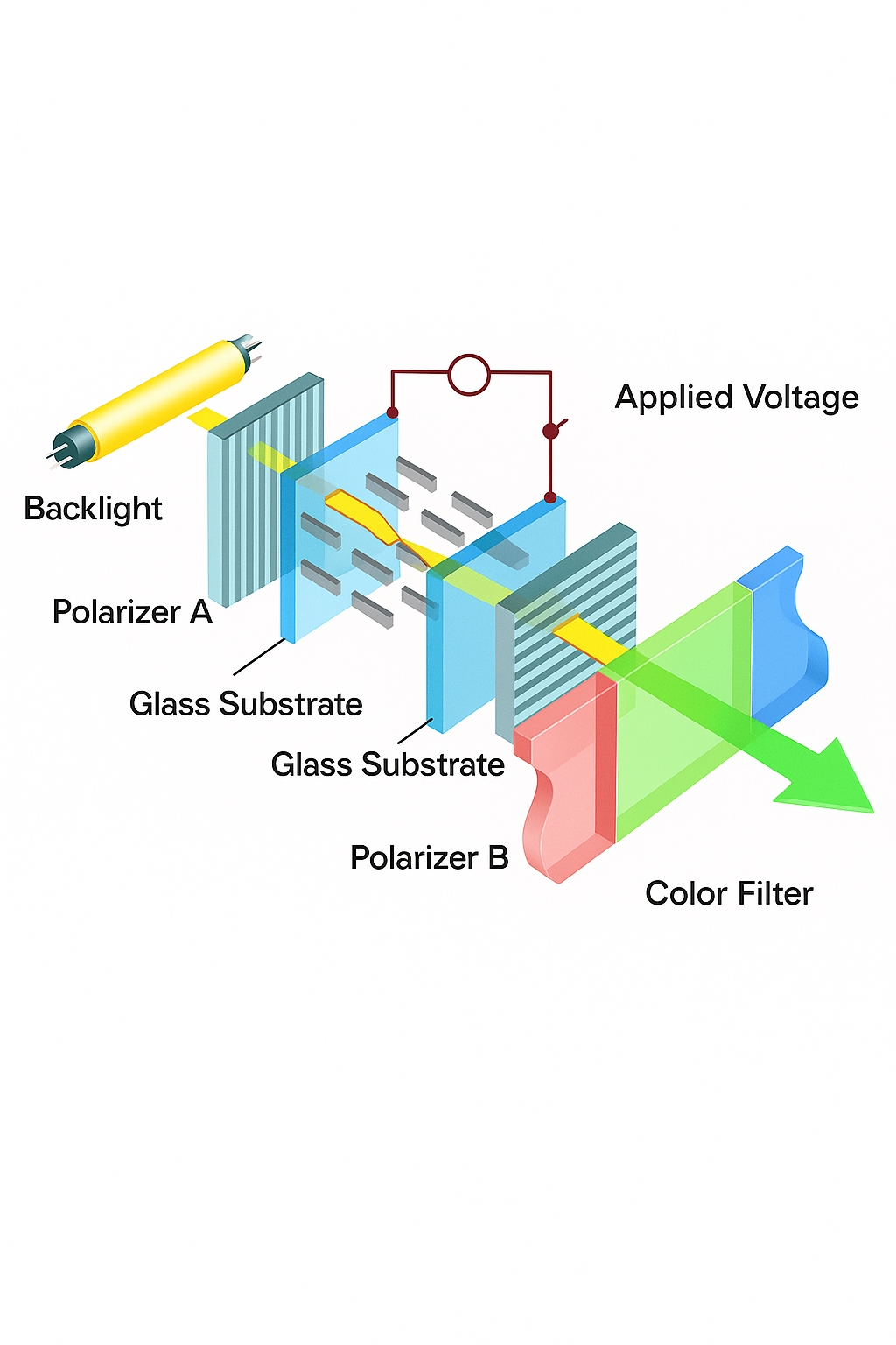
LCD display: Liquid crystal display, abbreviated LCD. Compared with CRTs, LCDs have lower power consumption, smaller size, higher information density, and are generally less strenuous to view, which makes them mainstream for TVs, computer monitors, mobile phone screens, and embedded displays. Liquid crystal is an organic material between solid and liquid states whose molecular order can be changed by electric fields. This property, together with polarizers and color filters, is used to control light transmission and generate red, green, and blue intensity components. A single display element combining the RGB components is called a pixel. Note: liquid crystals are not emissive, so a backlight is required.
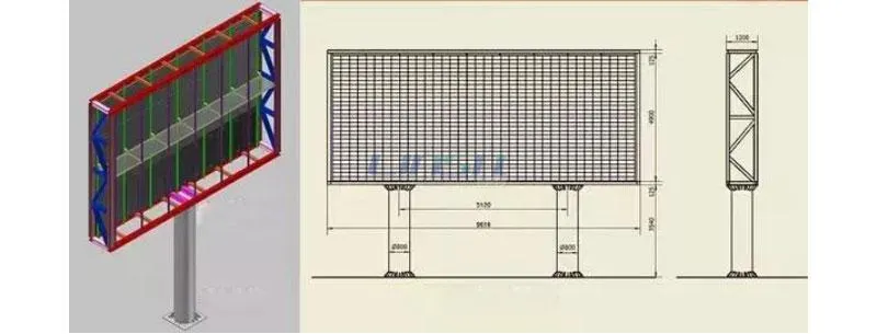
LED display: A full-color LED dot-matrix pixel contains red, green, and blue LED emitters. By controlling the intensity of each LED, full-color output is achieved. Because the LEDs are self-emissive, outdoor visibility in daylight is excellent; however, LED packages are relatively large so pixel density is low, making them suitable for large outdoor screens. Single-color LED dot-matrix displays are common for applications such as bus information signs and shop signage.
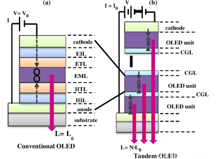
OLED display: OLED is similar in principle to LED dot-matrix displays but uses organic light-emitting diodes as pixels, providing much higher pixel density. OLEDs do not require a backlight, and they offer high contrast, thin form factor, wide viewing angle, and fast response. As manufacturing matures, OLED technology is becoming more widely used.
2. Basic display parameters
Pixel: The smallest image element on a display.
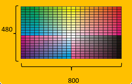
Resolution: Often expressed as "columns x rows" for embedded displays. For example, 800x480 means 800 pixels per row and 480 pixels per column.
Color depth: The number of colors each pixel can represent, usually measured in bits. A monochrome display has 1 bit per pixel (on/off). Common color depths are 16-bit and 24-bit. RGB565 is 16-bit (5 bits red, 6 bits green, 5 bits blue), while RGB888 is 24-bit (8 bits per color).
Display size: Typically given in inches and refers to the diagonal length. The actual width and height depend on the diagonal length and aspect ratio.
Frame buffer (VRAM): Each pixel's data is stored in memory for transfer to the display. This memory is called the frame buffer or video RAM. External LCD controllers often include frame buffer memory. Microcontrollers with integrated LCD controllers can use internal SRAM or external SDRAM for frame buffer space.
Example: For an 800x480 display using RGB888, one frame size is 3 bytes x 800 x 480 = 1,152,000 bytes. Using RGB565, one frame is 2 bytes x 800 x 480 = 768,000 bytes.
3. TFT-LCD control block
Some microcontrollers integrate an LCD controller so no external controller is required. For example, the STM32F429 series integrates an LCD controller, similar to an integrated GPU. Other MCUs without an integrated LCD controller must drive panels that include their own controller chip.
For panels with a controller, the MCU writes data to the controller's frame buffer and the controller drives the panel. For panels without a controller (driven directly by an MCU with an integrated controller), the MCU reserves part of its memory as the frame buffer.
4. TFT-LCD control principles
TFT-LCD assembly typically consists of the liquid crystal display panel, a capacitive touch panel, and a PCB backplane.
- Display panel: Color device used for image and text rendering.
- Touch panel: Includes a touch controller that processes touch signals and communicates via signal lines. The touch surface is transparent and is laminated onto the LCD.
- PCB backplane: May include an LCD controller chip. Many low-end MCUs cannot directly drive an LCD panel and require a dedicated LCD controller; the external MCU sends display data to that controller. Some panels without a controller have only power management circuits on the PCB and connect the panel signals directly to the external MCU.
5. RGB-LCD control basics
RGB signal lines: There are separate data lines for the red, green, and blue components. For example, RGB565 uses 5 red, 6 green, and 5 blue lines (16 bits total). RGB888 uses 8 lines per color (24 bits total).
Clock signal (CLK): The display and host use synchronous communication. Each clock cycle transfers data for one pixel.
Horizontal sync (HSYNC): Indicates the end of a line. For a 800x480 display, HSYNC toggles 480 times per frame transfer.
Vertical sync (VSYNC): Indicates the end of a frame. VSYNC toggles once per frame. Frame rate, in frames per second, describes how many frames the display shows per second. For 60 fps, VSYNC toggles 60 times per second.
Data enable (DE): Indicates data validity. When DE is high, the RGB data lines carry valid pixel data.
Data transfer timing: One VSYNC (a frame) contains many HSYNC events (lines), and each HSYNC contains many pixel data words (each 24-bit or 16-bit depending on format).
The display has a scanning pointer that advances left-to-right, top-to-bottom. Pixel data is sent over the RGB bus under the CLK signal. HSYNC toggles at the end of each line, VSYNC toggles at the end of each frame. Between lines and frames the display requires blanking intervals and timing margins described in panel specifications.
Timing parameters such as front porch, back porch, sync widths, and total periods must be set correctly. These parameters affect refresh behavior and perceived smoothness. Typical timing parameters are provided by the panel manufacturer.
6. SSD1963 LCD controller
LCD driver chips or display drivers include internal buffers for storing text and graphics data and can feed the LCD module at high speed. The main job of an LCD driver is to convert host data/commands into per-pixel RGB data for display. Common driver chips include ILI932, ILI9328, SSD1963, HX8347, ILI9341, and NT5510.
SSD1963 features: internal 1215 KB frame buffer, supports up to 864x480 resolution, supports 24bpp RGB888. In the following examples a 4.3-inch TFT true-color screen (480x272) using RGB565 will be used.
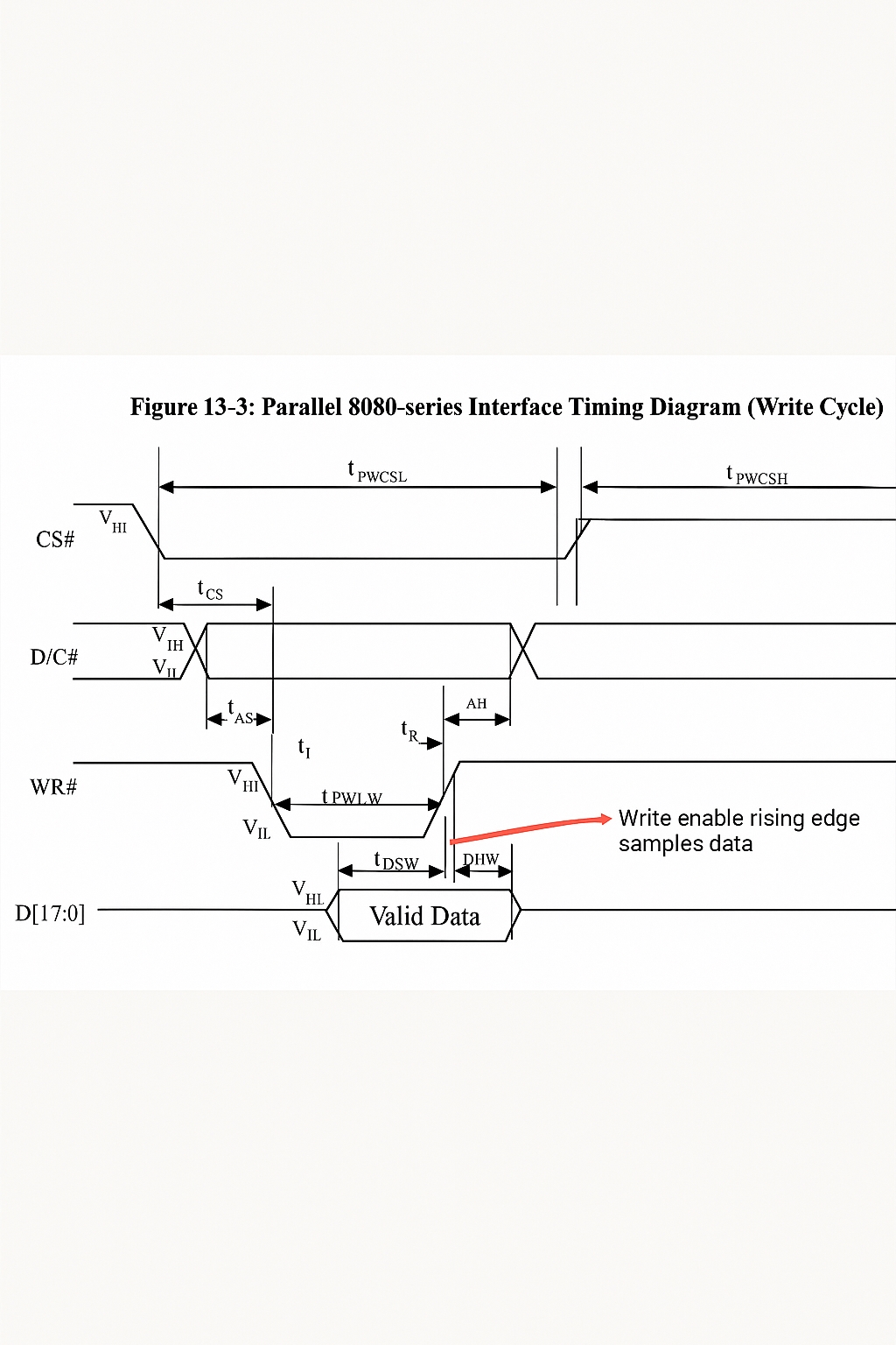
When pin resources permit, the parallel 8080-style interface provides higher transfer efficiency than SPI, so 8080 timing is used when possible.
8080 write timing example:
// Use GPIO pins to emulate 8080 timing
void LCD_WR_Byte(uint8_t dat, uint8_t cmd){
    LCD_Data_Out(dat);        // Put data
    if(cmd) LCD_DC_Set();     // Send command
    else    LCD_DC_Clr();     // Send data
    LCD_CS_Clr();             // Pull CS low
    LCD_WR_Clr();             // Write enable
    LCD_WR_Set();             // WR rising edge, latch data
    LCD_CS_Set();             // Release CS
    LCD_DC_Set();             // Reset DC line
}
Note: The STM32 communicates with the SSD1963 via the 8080 interface to control the display. Communications include commands and frame buffer data; frame buffer data encodes pixel values (e.g., RGB565). Commands control SSD1963 operations such as reset, set cursor, and sleep.
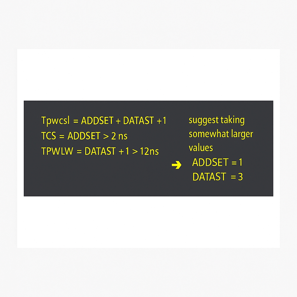
FSMC can be used to emulate 8080 timing. The important timing parameters must be tuned to avoid long refresh times that cause perceptible lag.
For FSMC and 8080, the first four signal lines are identical. FSMC address line A0 corresponds to the 8080 D/C# signal. When A0 is high the controller interprets the bus as data; when A0 is low it interprets the bus as a command. The LCD controller CS is connected to FSMC NE4, so addresses mapped under NE4 will select the LCD controller. Address calculations must account for the MCU internal AHB bus using byte addressing and the external memory word addressing; the effective address is shifted according to data width. For example:
- 0x6C000000 -> low indicates command
- 0x6C000002 -> high indicates data
LCD test procedure
- Configure RCC.
- Configure FSMC and timing according to panel parameters (units typically in ns). Values must be tuned for the development platform.
- Programming.
// lcd.c
#include "lcd.h"
#include "font.h"
#include "stdlib.h"

#define MAX_HZ_POSX 480
#define MAX_HZ_POSY 227

#define LCD_RAM    *( (__IO uint16_t *) (0x6C000002) )    // data register
#define LCD_REG    *( (__IO uint16_t *) (0x6C000000) )    // command register

#define rw_data_prepare()               write_cmd(34)

void write_cmd(unsigned short cmd);
unsigned short read_data(void);
unsigned short DeviceCode;

void write_cmd(unsigned short cmd){
    LCD_REG = cmd;
}

unsigned short read_data(void){
    unsigned short temp;
    temp = LCD_RAM;
    temp = LCD_RAM;
    return temp;
}

void write_data(unsigned short data_code ){
    LCD_RAM = data_code;
}

void write_reg(unsigned char reg_addr, unsigned short reg_val){
    write_cmd(reg_addr);
    write_data(reg_val);
}

unsigned short read_reg(unsigned char reg_addr){
    unsigned short val = 0;
    write_cmd(reg_addr);
    val = read_data();
    return val;
}

void lcd_SetCursor(unsigned int x, unsigned int y){
    write_reg(0x004e, x);    /* 0-239 */
    write_reg(0x004f, y);    /* 0-319 */
}

/* Read GRAM at specified address */
static unsigned short lcd_read_gram(unsigned int x, unsigned int y){
    unsigned short temp;
    lcd_SetCursor(x, y);
    rw_data_prepare();
    /* dummy read */
    temp = read_data();
    temp = read_data();
    return temp;
}

static void lcd_data_bus_test(void){
    unsigned short temp1;
    unsigned short temp2;
    /* write */
    lcd_SetCursor(0,0);
    rw_data_prepare();
    write_data(0x5555);
    lcd_SetCursor(1,0);
    rw_data_prepare();
    write_data(0xAAAA);
    /* read */
    lcd_SetCursor(0,0);
    temp1 = lcd_read_gram(0,0);
    temp2 = lcd_read_gram(1,0);
    if( (temp1 == 0x5555) && (temp2 == 0xAAAA) ){
        // data bus test pass
    }else{
        // data bus test error
    }
}

void lcd_clear(unsigned short Color){
    unsigned int count;
    write_cmd(0x002a); // send column address: start-end
    write_data(0);    write_data(0);
    write_data(HDP >> 8);    write_data(HDP & 0x00ff);
    write_cmd(0x002b); // send row address: start-end
    write_data(0);    write_data(0);
    write_data(VDP >> 8);    write_data(VDP & 0x00ff);
    write_cmd(0x002c); // write frame buffer command
    for(count = 0; count < 130560; count++){
        write_data(Color);
    }
}

void lcd_init(void){
    HAL_Delay(50);
    DeviceCode = read_reg(0x0000);
    write_cmd(0x002b);
    write_data(0);
    HAL_Delay(50); // delay 50 ms

    write_cmd(0x00E2); // PLL multiplier, set PLL clock
    write_data(0x001D); // example values
    write_data(0x0002);
    write_data(0x0004);

    write_cmd(0x00E0); // PLL enable
    write_data(0x0001);
    HAL_Delay(10);
    write_cmd(0x00E0);
    write_data(0x0003);
    HAL_Delay(12);
    write_cmd(0x0001);  // software reset
    HAL_Delay(10);

    write_cmd(0x00E6); // PLL setting for PCLK, depends on resolution
    write_data(0x0000);
    write_data(0x00D9);
    write_data(0x0016);

    write_cmd(0x00B0); // LCD SPECIFICATION
    write_data(0x0020);
    write_data(0x0000);
    write_data((HDP >> 8) & 0X00FF); // Set HDP
    write_data(HDP & 0X00FF);
    write_data((VDP >> 8) & 0X00FF); // Set VDP
    write_data(VDP & 0X00FF);
    write_data(0x0000);

    write_cmd(0x00B4); // HSYNC
    write_data((HT >> 8) & 0X00FF); // Set HT
    write_data(HT & 0X00FF);
    write_data((HPS >> 8) & 0X00FF); // Set HPS
    write_data(HPS & 0X00FF);
    write_data(HPW); // Set HPW
    write_data((LPS >> 8) & 0X00FF); // Set LPS
    write_data(LPS & 0X00FF);
    write_data(0x0000);

    write_cmd(0x00B6); // VSYNC
    write_data((VT >> 8) & 0X00FF);   // Set VT
    write_data(VT & 0X00FF);
    write_data((VPS >> 8) & 0X00FF); // Set VPS
    write_data(VPS & 0X00FF);
    write_data(VPW); // Set VPW
    write_data((FPS >> 8) & 0X00FF);
    write_data(FPS & 0X00FF);

    write_cmd(0x00BA);
    write_data(0x0005); // GPIO config
    write_cmd(0x00B8);
    write_data(0x0007); // GPIO direction
    write_data(0x0001); // GPIO normal

    write_cmd(0x0036); // rotation
    write_data(0x0000);
    HAL_Delay(50);

    write_cmd(0x00BE); // set PWM for backlight
    write_data(0x0006);
    write_data(0x0080);
    write_data(0x0001);
    write_data(0x00f0);
    write_data(0x0000);
    write_data(0x0000);

    write_cmd(0x00d0); // dynamic backlight control
    write_data(0x000d);
    write_cmd(0x00F0); // pixel data interface
    write_data(0x0003); // 03:16-bit
    write_cmd(0x0029); // display on

    lcd_clear(Yellow); // initialize screen fill color
}

/* Function name: LCD_SetCursor
   Description: set cursor position */
void LCD_SetCursor(uint16_t Xpos, uint16_t Ypos){
    write_cmd(0x002A);
    write_data(Xpos >> 8);    write_data(Xpos & 0x00ff);
    write_data(479 >> 8);    write_data(479 & 0x00ff);
    write_cmd(0x002b);
    write_data(Ypos >> 8);    write_data(Ypos & 0x00ff);
    write_data(271 >> 8);    write_data(271 & 0x00ff);
}

/* Draw a point */
void LCD_DrawPoint(uint16_t xsta, uint16_t ysta, uint16_t color){
    LCD_SetCursor(xsta, ysta);  /* set cursor position */
    rw_data_prepare();          /* start writing GRAM */
    write_data(color);
}

/* Display a 16x16 Chinese glyph from mask */
void WriteOneHz(uint16_t x0, uint16_t y0, uint8_t *pucMsk, uint16_t PenColor, uint16_t BackColor){
    uint16_t i, j;
    uint16_t mod[16];                                      /* current glyph 16*16 */
    uint8_t *pusMsk;                                       /* glyph data pointer */
    uint16_t y;
    pusMsk = pucMsk;
    for(i = 0; i < 16; i++){                   /* save current glyph */
        mod[i] = (*pusMsk << 8) | (*(pusMsk + 1));  /* combine bytes for half-word aligned access */
        pusMsk = pusMsk + 2;
    }
    for(i = 0; i < 16; i++){                                    /* 16 rows */
        for(j = 0; j < 16; j++){                                /* 16 columns */
            if((mod[i] << j) & 0x8000){       /* display the bit */
                LCD_DrawPoint(x0 + j, y0 + i, PenColor);
            } else {
                LCD_DrawPoint(x0 + j, y0 + i, BackColor);
            }
        }
    }
}

/* find character index in custom GBK font */
uint16_t findHzIndex(uint8_t *hz){
    uint16_t i = 0;
    FNT_GB16 *ptGb16 = (FNT_GB16 *)GBHZ_16; /* ptGb16 points to GBHZ_16 */
    while(ptGb16[i].Index[0] > 0x80){
        if (( *hz == ptGb16[i].Index[0]) && (*(hz + 1) == ptGb16[i].Index[1])){
            return i;
        }
        i++;
        if(i > (sizeof((FNT_GB16 *)GBHZ_16) / sizeof(FNT_GB16) - 1)){ /* search bounds */
            break;
        }
    }
    return 0;
}

/* Show a Chinese string */
void LCD_ShowHzString(uint16_t x0, uint16_t y0, uint8_t *pcStr, uint16_t PenColor, uint16_t BackColor){
    uint16_t usIndex;
    uint8_t size = 16;
    FNT_GB16 *ptGb16 = 0;
    ptGb16 = (FNT_GB16 *)GBHZ_16;
    if(x0 > MAX_HZ_POSX){ x0 = 0; y0 += size; } /* wrap line */
    if(y0 > MAX_HZ_POSY){ y0 = x0 = 0; lcd_clear(White); } /* wrap and clear */
    usIndex = findHzIndex(pcStr);
    WriteOneHz(x0, y0, (uint8_t *)&(ptGb16[usIndex].Msk[0]), PenColor, BackColor); /* display char */
}

/* Show ASCII character */
void LCD_ShowChar(uint16_t x, uint16_t y, uint8_t num, uint8_t size, uint16_t PenColor, uint16_t BackColor){
    #define MAX_CHAR_POSX (272-8)
    #define MAX_CHAR_POSY (480-16)
    uint8_t temp;
    uint8_t pos, t;
    if(x > MAX_CHAR_POSX || y > MAX_CHAR_POSY) return;
    num = num - ' ';                         /* get offset */
    for(pos = 0; pos < size; pos++){
        if(size == 12) temp = asc2_1206[num][pos]; /* 1206 font */
        else temp = asc2_1608[num][pos]; /* 1608 font */
        for(t = 0; t < size / 2; t++){
            if(temp & 0x01) /* from LSB */
                LCD_DrawPoint(x + t, y + pos, PenColor);
            else
                LCD_DrawPoint(x + t, y + pos, BackColor);
            temp >>= 1;
        }
    }
}

/* Show ASCII string */
void LCD_ShowCharString(uint16_t x, uint16_t y, const uint8_t *p, uint16_t PenColor, uint16_t BackColor){
    uint8_t size = 16;     /* default font size 16 */
    if(x > MAX_HZ_POSX){ x = 0; y += size; } /* wrap line */
    if(y > MAX_HZ_POSY){ y = x = 0; lcd_clear(White); }
    LCD_ShowChar(x, y, *p, size, PenColor, BackColor);
}

/* Show mixed string (ASCII and GBK) */
void LCD_ShowString(uint16_t x0, uint16_t y0, uint8_t *pcStr, uint16_t PenColor, uint16_t BackColor){
    while(*pcStr != '?'){
        if(*pcStr > 0x80){ /* display Chinese */
            LCD_ShowHzString(x0, y0, pcStr, PenColor, BackColor);
            pcStr += 2;
            x0 += 16;
        } else { /* display ASCII */
            LCD_ShowCharString(x0, y0, pcStr, PenColor, BackColor);
            pcStr += 1;
            x0 += 8;
        }
    }
}

/* write data prepare */
void write_data_Prepare(void){
    write_cmd(0x002C);
}

/* Set window */
void LCD_WindowMax(unsigned int xsta, unsigned int xend, unsigned int ysta, unsigned int yend){
    write_cmd(0x002A);
    write_data(xsta >> 8); write_data(xsta & 0X00FF);
    write_data(xend >> 8); write_data(xend & 0X00FF);
    write_cmd(0x002B);
    write_data(ysta >> 8); write_data(ysta & 0X00FF);
    write_data(yend >> 8); write_data(yend & 0X00FF);
}

/* Fill window with color */
void LCD_Fill(uint16_t xsta, uint16_t xend, uint16_t ysta,  uint16_t yend, uint16_t colour){
    uint32_t n;
    LCD_WindowMax(xsta, xend, ysta, yend);
    write_data_Prepare();         /* start writing GRAM */
    n = (uint32_t)(yend - ysta + 1) * (xend - xsta + 1);
    while(n--) { write_data(colour); } /* output fill color */
}

/* Draw line between two points */
void LCD_DrawLine(uint16_t xsta, uint16_t xend, uint16_t ysta, uint16_t yend, uint16_t color){
    uint16_t x, y, t;
    if((xsta == xend) && (ysta == yend)) LCD_DrawPoint(xsta, ysta, color);
    else if(abs(yend - ysta) > abs(xend - xsta)) { // slope > 1
        if(ysta > yend) { t = ysta; ysta = yend; yend = t; t = xsta; xsta = xend; xend = t; }
        for(y = ysta; y < yend; y++){
            x = (uint32_t)(y - ysta) * (xend - xsta) / (yend - ysta) + xsta;
            LCD_DrawPoint(x, y, color);
        }
    } else { // slope <= 1
        if(xsta > xend){ t = ysta; ysta = yend; yend = t; t = xsta; xsta = xend; xend = t; }
        for(x = xsta; x <= xend; x++){
            y = (uint32_t)(x - xsta) * (yend - ysta) / (xend - xsta) + ysta;
            LCD_DrawPoint(x, y, color);
        }
    }
}

/* Draw circle using Bresenham algorithm */
void Draw_Circle(uint16_t x0, uint16_t y0, uint8_t r, uint16_t color){
    int a, b;
    int di;
    a = 0; b = r;
    di = 3 - (r << 1);             /* next point decision variable */
    while(a <= b){
        LCD_DrawPoint(x0 - b, y0 - a, color); // ...
        LCD_DrawPoint(x0 + b, y0 - a, color);
        LCD_DrawPoint(x0 - a, y0 + b, color);
        LCD_DrawPoint(x0 - a, y0 - b, color);
        LCD_DrawPoint(x0 + b, y0 + a, color);
        LCD_DrawPoint(x0 + a, y0 - b, color);
        LCD_DrawPoint(x0 + a, y0 + b, color);
        LCD_DrawPoint(x0 - b, y0 + a, color);
        a++;
        if(di < 0) di += 4 * a + 6;
        else { di += 10 + 4 * (a - b); b--; }
        LCD_DrawPoint(x0 + a, y0 + b, color);
    }
}

/* Draw rectangle */
void LCD_DrawRectangle(uint16_t xsta, uint16_t xend, uint16_t ysta, uint16_t yend, uint16_t color){
    LCD_DrawLine(xsta, xend, ysta, ysta, color);
    LCD_DrawLine(xsta, xsta, ysta, yend, color);
    LCD_DrawLine(xsta, xend, yend, yend, color);
    LCD_DrawLine(xend, xend, ysta, yend, color);
}

/* Draw picture in specified coordinates.
   Image format: horizontal scan, 16-bit color */
void LCD_DrawPicture(uint16_t StartX, uint16_t Xend, uint16_t StartY, uint16_t Yend, uint8_t *pic){
    static uint16_t i = 0, j = 0;
    uint16_t *bitmap = (uint16_t *)pic;
    for(j = 0; j < Yend - StartY; j++){
        for(i = 0; i < Xend - StartX; i++)
            LCD_DrawPoint(StartX + i, StartY + j, *bitmap++);
    }
}