What is a 4-20 mA loop and how does it work?
What is a 4-20 mA loop? How does it work?
In industrial processes, measurement loops include sensor input, such as sensor input, temperature, pressure, and flow. The measured process variable is converted to a signal that is transmitted to other units in the loop, for example an indicator and a controller. The controller then interprets the signal and issues control actions to process final elements such as valves.
Control loops can be analog or discrete.
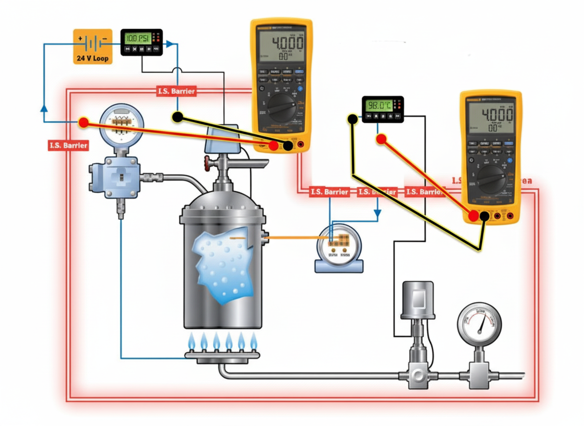
Basic components of a 4-20 mA control loop
24 V power supply
Transmitter that controls a 4-20 mA signal proportional to the process variable
Indicator that converts the 4-20 mA signal to a corresponding process variable
The indicator or controller I/O uses a 250 ohm input resistor to produce a 1-5 V input signal (Ohm's law: Voltage = Current * Resistance, 4-20 mA × 250 ohms = 1-5 V)
Temperature and pressure transmitters in the loop
Temperature transmitters in the loop typically measure the temperature of the process medium, such as a fluid. Usually they convert a thermocouple or RTD sensor signal to a 4-20 mA output. The controller then converts the 4-20 mA back to a temperature value. Based on that temperature, the control loop issues commands to final control elements.
Similarly, pressure transmitters measure the pressure of the process medium. The sensor senses the pressure and the transmitter converts that to a 4-20 mA signal. The controller decodes the 4-20 mA into a pressure value and sends commands to valves to maintain safe pressure in vessels.
Common control loop faults and causes
- Wiring and terminal issues: bad terminals, insulation failures, cable corrosion and contamination.
- Loop power supply problems: noise interference, overvoltage, and other abnormal supply conditions.
- Control system I/O card failures.
- Transmitter faults.
- Sensor faults: damaged elements or blocked sensing paths.
Loop troubleshooting steps
1. Verify the 4-20 mA signal
- Measure the 4-20 mA signal using a series method or a milliamp clamp meter.
- Verify the power supply.
- Inspect wiring for faults.
- Check I/O for faults.
- Inspect wiring terminals for problems.
Troubleshooting procedure:
Measure the loop current. If the measurement is 0 mA, continue deeper troubleshooting. If the controller shows no indication, the I/O input fuse may have blown and the loop is open. Verify by measuring across the 250 ohm input.
2. Controller I/O troubleshooting: 4-20 mA loop substitution test
Transmitter substitution is an effective I/O fault analysis method. Use a test device to output a known standard signal to verify controller input and loop behavior.
Troubleshooting procedure:
- Disconnect the transmitter and connect a loop calibrator or process simulator at the transmitter terminals.
- Set the milliamp output and sweep the range from 4 to 20 mA.
- Verify the indicator reading. This test simultaneously verifies wiring, power supply, and I/O.
- If the controller still shows no indication, check the I/O input fuse for an open circuit. This can be verified by measuring across the 250 ohm input.
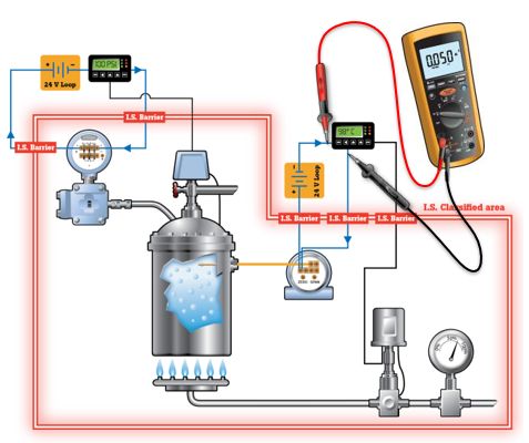
3. Power supply troubleshooting
Use a loop calibrator or a multimeter to measure the loop supply voltage.
Troubleshooting procedure:
- Measure the supply; it should be approximately 24 V.
- If measurements are inconclusive, perform a substitution test:
- 1) Disconnect the device loop power.
- 2) Connect the 24 V loop supply of the calibrator or process simulator at that point.
- 3) If the problem is resolved, the device loop power may be faulty or overloaded.
4. Wiring noise troubleshooting
Causes of wiring noise include poor insulation, cable shield failure, grounding loop faults, noisy power supplies, and wiring errors. Capture and confirm noise using a process multimeter with AC measurement capability, a handheld oscilloscope, or a multimeter. Under normal conditions only a few millivolts of AC should be present in the system.
Recommended troubleshooting tools
| Variable to measure or simulate | Tools for measurement or output | What the technician should verify |
|---|---|---|
| Measure 4-20 mA signal | Multimeter, loop calibrator | Is the measured milliamp value as expected? |
| Source 4-20 mA signal | Loop calibrator | Is the I/O or other milliamp input device functioning? Are supply, wiring, and I/O correct? |
| Measure 24 V loop voltage | Multimeter | Is a complete 24 V supply available? Are there defects or overloads? |
| Provide 24 V loop supply | Loop calibrator | Substitution test for fixed-supply instruments: does the loop require an external supply? |
| Output 0-10 V, 1-5 V signals | Loop calibrator with voltage output or specific milliamp clamp meter | Is the I/O or other voltage input device functioning? |
| Continuity measurement | Multimeter, process meter, multifunction process calibrator | Find shorts, bad terminals, resistive wiring connections, and wiring errors |


