Scope
CS114 specifies the current injection conducted susceptibility test for cable bundles. It applies to all interconnect cables, including power cables. The test frequency range in the U.S. standards is 10 kHz to 200 MHz (GJB151B specifies 10 kHz to 400 MHz; testing between 200 MHz and 400 MHz may encounter resonances that affect repeatability, so testing that band is subject to the purchaser's decision). For items installed on surface ships or submarines, if the power source is a solid-state power supply, an additional common-mode disturbance test is required on the complete power cable loop from 4 kHz to 1 MHz with a limit of 77 dBμA.
Purpose
The purpose of CS114 is to verify the immunity of the item under test to RF interference coupled onto cables attached to the item. This procedure does not apply to coaxial cables connected to receiver antenna ports, except for surface ships and submarines.
Standards Text Comparison
There are different interpretations of the CS114 test in military and national standards. To clarify the test method, it helps to compare key textual descriptions from the standards. Below are the excerpts and calibration limit curves from three standards for comparison.
MIL-STD-461F
The highlighted portion in the standard is clear in English but may be subject to differing interpretations.
Calibration limit curves for the different test levels defined in MIL-STD-461F:
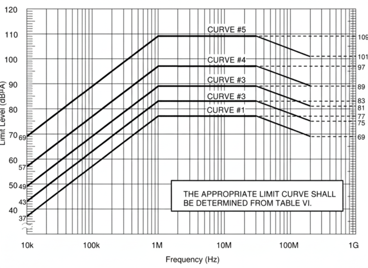
Figure 1: CS114 calibration limit curves in MIL-STD-461F
MIL-STD-461G
(Excerpt image)
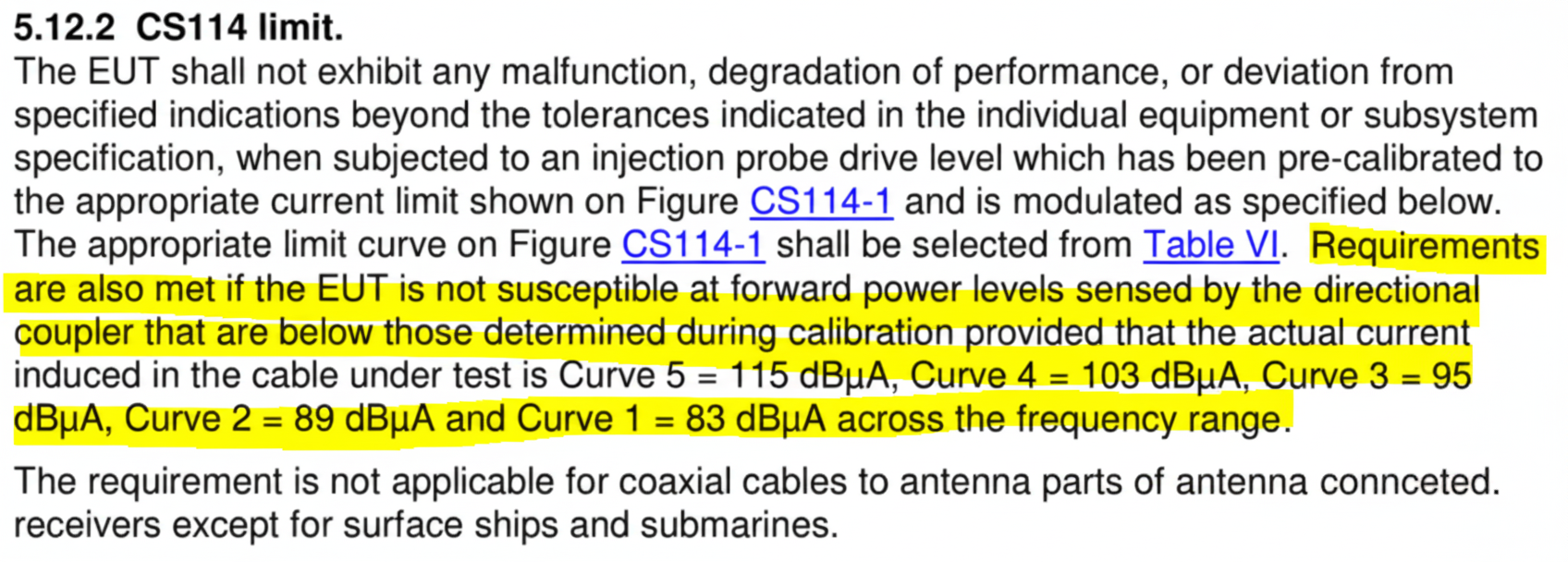
I highlighted a section that, while clearly worded, could be debated. Compared with the F version, does this G text differ in essential meaning?
Calibration limit curves for the different test levels defined in MIL-STD-461G.
GJB151B-2003
Compared with the MIL-STD-461F and 461G excerpts, is the essential meaning different?
The calibration limit curves defined in GJB151B-2003 differ mainly by extending the frequency range to 400 MHz.
After comparing the key passages in these three standards, the differences are clearer. The following sections describe calibration and test methods for CS114.
Calibration and Verification
In short, the calibration methods are the same across the standards. Connect the equipment and accessories as shown in Figures 4 or 5, and perform calibration according to the calibration limit curves for each test level. For each frequency point, record the forward power required to achieve the target current; this becomes the calibration file. GJB151B-2003 uses the same calibration setup as MIL-STD-461F, as shown in Figure 4. MIL-STD-461G includes the current monitoring probe in the calibration chain, which is a more complete approach, as shown in Figure 5.
MIL-STD-461G also adds a verification step after calibration. Using the same connection setup, transmit the calibrated forward power and verify that the current measured by the current monitoring probe is within a 3 dB error band of the calibrated value.
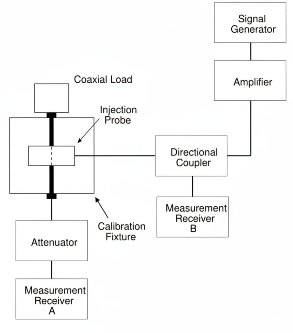
Figure 2: CS114 calibration setup from MIL-STD-461F
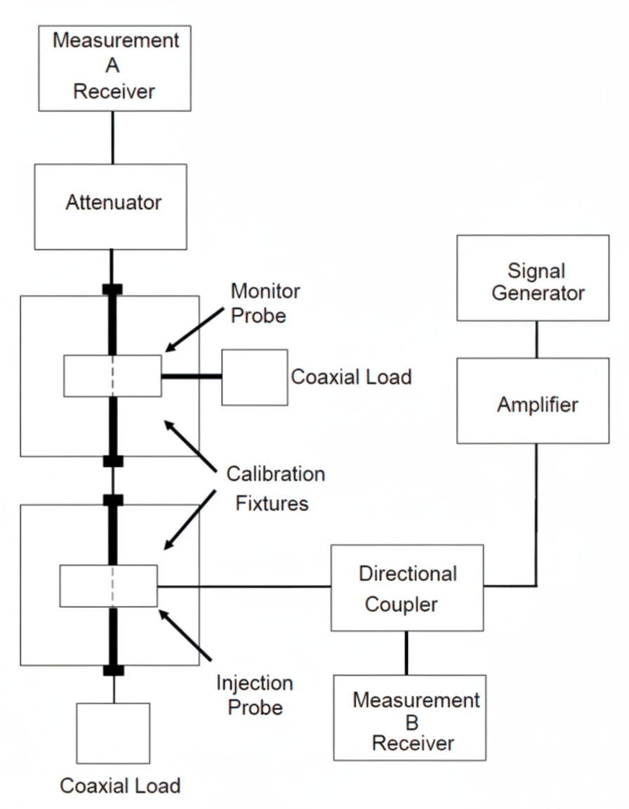
Figure 3: CS114 calibration setup from MIL-STD-461G
Test Procedure
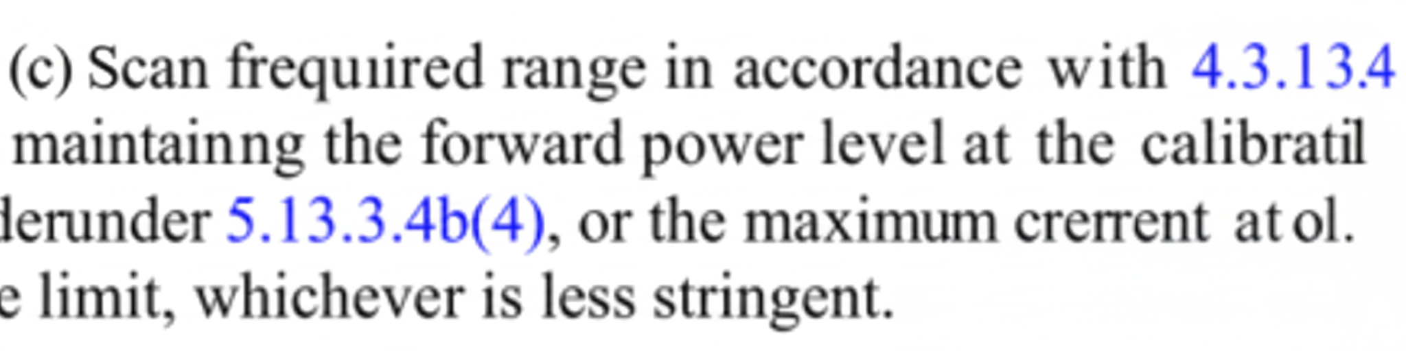
MIL-STD-461F describes the test method as follows:
The CS114 descriptions in MIL-STD-461F and MIL-STD-461G are consistent; there is no substantive difference between them.
The highlighted text in that excerpt is consistent with the earlier related passage.
Closed-Loop or Substitution Method?
Based on the standard descriptions above, the intended CS114 test method can be determined. The standards emphasize practical implementability, so procedures were written to be achievable in test labs. Given the calibration and verification steps described, implementers should follow the calibration chain and verification requirements specified by the applicable standard to ensure correct application of either closed-loop feedback or substitution approaches as required.
Notes
EMC testing is an experimental discipline that must be realized with concrete measurement procedures. Standard writers take implementability into account when specifying tests and calibration methods.


