Introduction
Differential pressure flowmeters are widely used in chemical processing and are commonly encountered by operators. They are based on the throttling principle: the pressure drop created by a flow restriction is used to determine flowrate.
Overview and Components
A typical differential pressure flow measurement system consists of three parts: a primary flow restriction installed in the process pipeline, impulse tubing, and a differential pressure transmitter. The primary element converts fluid flow into a differential pressure signal, and the differential pressure instrument or transmitter measures that pressure difference and provides an indication.
Common primary elements include orifice plates and nozzles. These flowmeters have a long history of industrial use and a substantial body of operational experience and test data.
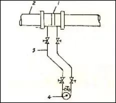
Figure 1. Differential pressure flowmeter components
Installation Requirements
Accurate measurement depends not only on correct selection and calculation, but also on proper installation of the primary element, impulse tubing, and differential pressure transmitter to ensure correct signal capture, transmission, and indication.
- Orifice plate alignment: The orifice plate must be concentric with the pipe axis and perpendicular to it. The sharp edge of the orifice plate must face the flow direction and must not be installed in reverse.
- Location on straight pipe: The orifice should be installed on a straight run of pipe. Nearby bends, valves, and other local resistances can affect measurement accuracy. Refer to instrument manuals or relevant references for required upstream and downstream straight pipe lengths.
- Liquid measurement: For liquid flow, pressure taps should be located on the lower half of the horizontal pipe, and the differential pressure transmitter should be installed below the orifice plate. If the transmitter must be above the primary element, install an air vent at the highest point of the impulse tubing to ensure no gas is trapped in the tubing.
- Gas measurement: For gas flow, pressure taps should be on the upper half of the pipe, and the differential pressure transmitter should be installed above the orifice plate. If this is not possible, install a condensation and drain valve at the lowest point of the impulse system to prevent liquid accumulation in the tubing.
- Steam measurement: For steam, pressure taps should be at the horizontal diameter of the pipe. A condensate pot must be installed near the orifice plate pressure taps so that steam condenses and the impulse tubing is filled with liquid. This separates the transmitter from high-temperature steam.
- Three-valve manifold: Install a three-valve manifold near the differential pressure transmitter (commonly above it), as shown in Figure 2.
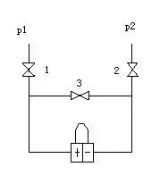
Figure 2. Three-valve manifold installation schematic
When configuring the three-valve manifold, observe two principles:
- Do not allow condensate or fill fluid in the impulse tubing to drain away.
- Do not subject the sensing element (diaphragm or bellows) to sudden overpressure or high temperature.
The startup sequence for the three-valve manifold should be: open the high-pressure valve 1, close the balance valve 2, then open the low-pressure valve 3. The shutdown sequence is the reverse: close low-pressure valve 3, open balance valve 2, then close high-pressure valve 1. Following this sequence avoids accidentally subjecting the measuring chamber to a sudden high-pressure condition that could damage the instrument.
Common Faults and Remedies
Symptom 1: Indicator at zero or barely moving
Possible causes:
- Balance valve not fully closed or leaking.
- High/low pressure valves at the primary element are not open.
- Valves or tubing between the primary element and the differential instrument are blocked.
- Steam impulse tubing has not fully condensed.
- Gasket between the primary element and the process pipe is not tight.
- Internal fault in the differential instrument.
Remedies:
- Close the balance valve; repair or replace if leaking.
- Open the high/low pressure valves.
- Flush the tubing; repair or replace valves.
- Allow complete condensation before opening the instrument.
- Tighten bolts or replace gasket.
- Inspect and repair the instrument.
Symptom 2: Indicator reads below zero
Possible causes:
- High/low pressure impulse lines are reversed.
- Signal wiring reversed.
- Severe leak or rupture on the high-pressure side tubing.
Remedies:
- Check and correct impulse line and signal wiring connections.
- Replace damaged components or tubing.
Symptom 3: Indicator reads low
Possible causes:
- High-pressure side tubing is leaking.
- Balance valve leaking or not fully closed.
- Air not fully vented from the high-pressure impulse line.
- Zero shift or drift in the differential instrument or secondary instruments.
- Mismatched primary element and differential instrument, not meeting design specifications.
Remedies:
- Check and eliminate leaks.
- Inspect, close, or repair the balance valve.
- Vent the air completely.
- Check and adjust zero settings.
- Replace with a correctly matched differential instrument.
Symptom 4: Indicator reads high
Possible causes:
- Low-pressure side tubing is leaking.
- Air accumulation on the low-pressure side tubing.
- Steam pressure below design value.
- Zero drift in the differential instrument.
- Mismatched primary element and differential instrument.
Remedies:
- Check and eliminate leaks.
- Vent trapped air.
- Apply density correction for actual conditions.
- Check and adjust zero.
- Replace with a correctly matched instrument.
Symptom 5: Indicator does not move
Possible causes:
- Freeze protection failed; hydraulic fill in the instrument or impulse tubing is frozen.
- High/low pressure valves not open.
Remedies:
- Improve freeze protection measures.
- Open the high/low pressure valves.
Symptom 6: Large indicator fluctuation
Possible causes:
- Large intrinsic flow fluctuations.
- Pressure-sensing element is overly sensitive to parameter fluctuations.
Remedies:
- Partially close the high/low pressure valves to dampen fluctuations.
- Adjust damping as appropriate.


