Introduction
A digital multimeter is a multifunction electronic measuring instrument that typically includes ammeter, voltmeter, and ohmmeter functions. It is sometimes called a multitester or multimeter. Understanding the principles and proper methods of measurement helps ensure correct and reliable readings. This article describes common measurements: resistance, DC and AC voltage, DC and AC current, diode testing, and transistor testing.
1. Resistance Measurement
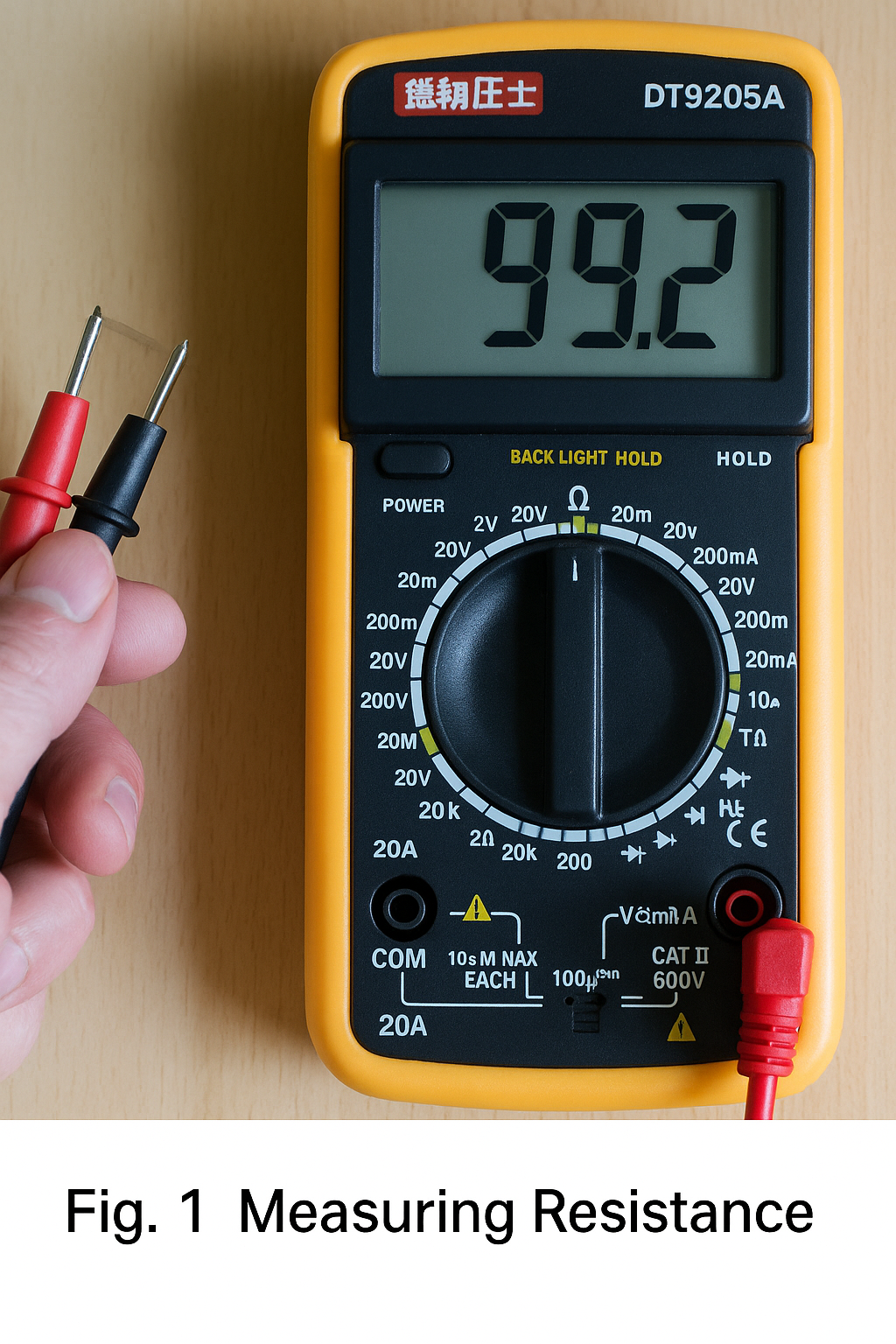
Steps: - Insert the red test lead into the VΩ terminal and the black test lead into the COM terminal. - Set the range selector to an appropriate "Ω" range. - Connect the red and black probes to the two metal ends of the resistor. - Read the value displayed on the screen.
Notes: - Range selection and switching: if the range is too small the display will show "1." and you should select a higher range. If the range is too large the display may show a number close to "0"; then select a lower range. - The displayed number combined with the range unit is the reading. For example, the "200" range uses "Ω", "2k" to "200k" use "kΩ", and "2M" to "2000M" use "MΩ". - If the measured resistance exceeds the selected range the meter displays "1", so choose a higher range. For resistances above 1 MΩ the reading may take several seconds to stabilize; this is normal. - When checking circuit impedance make sure to remove all power sources and discharge all capacitors in the circuit. Any power or energy-storage components will affect impedance measurements. - For the 200 MΩ range the meter shows an offset of 10 counts on short circuit; when measuring a large resistor subtract these 10 counts from the displayed reading. For example, if the display shows 101.0 on the 200 MΩ range, subtract 10 to get 100.0 MΩ actual resistance.
2. DC Voltage Measurement
Steps: - Insert the red lead into the VΩ terminal and the black lead into COM. - Set the range selector to an appropriate DC voltage position (usually marked V-). - Connect the probes to the two terminals of the power source or circuit and keep stable contact. - Read the displayed value.
Notes: - Always set the selector to a range higher than the estimated value. DC ranges are typically marked V-; AC ranges are V~. - If the display shows "1." the range is too small; increase the range. - A negative sign on the left indicates probe polarity is reversed: the red probe is on the negative terminal.
3. AC Voltage Measurement
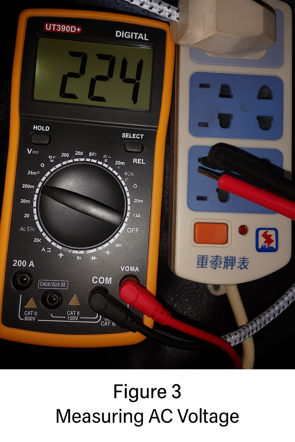
Steps: - Insert the red lead into VΩ and the black lead into COM. - Set the range selector to the appropriate AC voltage position (V~). - Connect the probes across the AC source and read the display.
Notes: - AC voltage has no polarity, so measurements are the same regardless of probe orientation. - For both AC and DC voltage, avoid touching the metal parts of the probes with your hands for safety.
4. DC Current Measurement
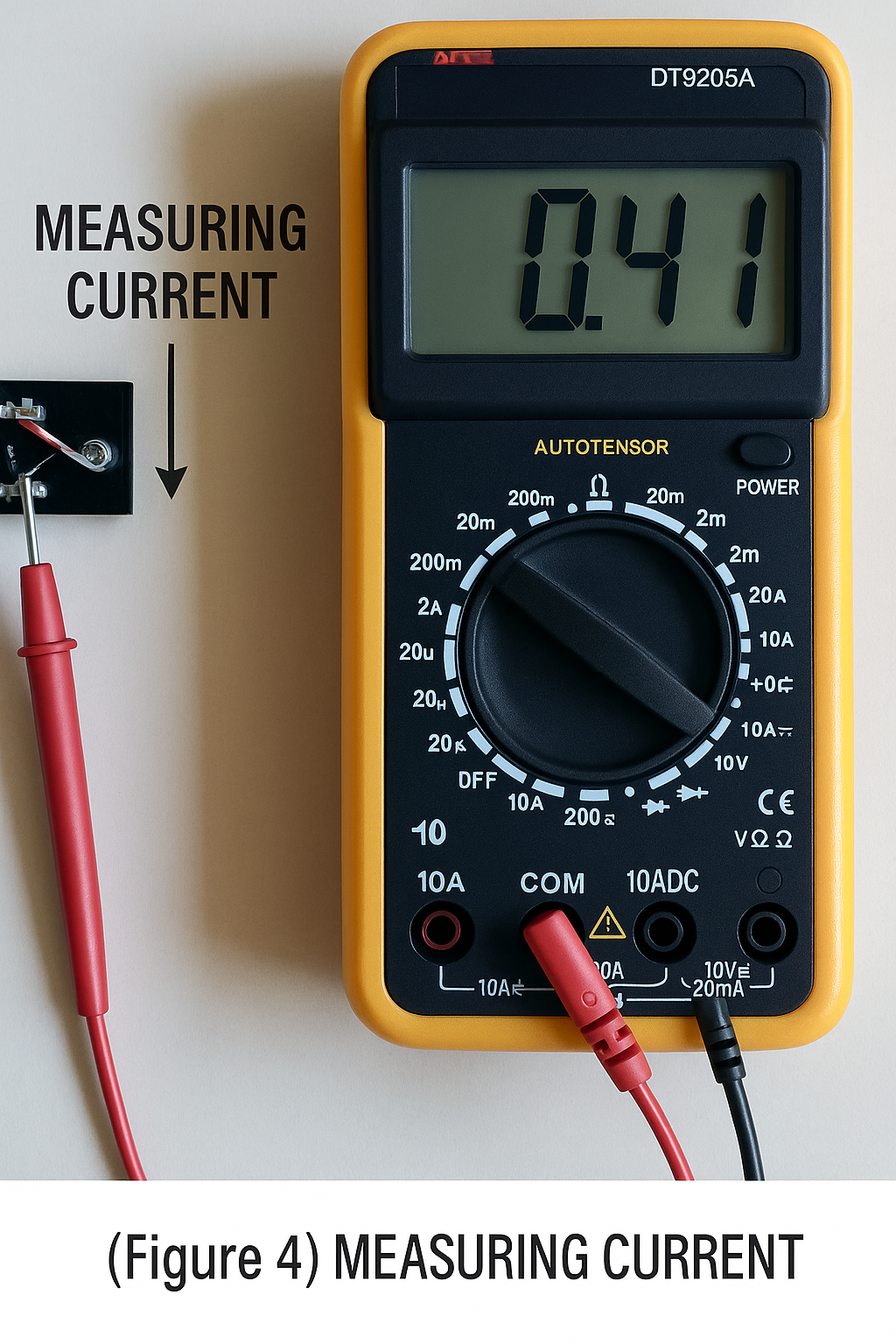
Steps: - Power off and open the circuit. - Insert the black lead into COM and the red lead into the mA or 20A terminal as appropriate. - Set the function switch to A- (DC) or A~ (AC) and choose a suitable range. - Break the circuit and connect the multimeter in series so current flows through the meter: current should enter the red probe and exit the black probe. - Power the circuit and read the LCD.
Notes: - Estimate the current magnitude first. For currents above 200 mA, use the 10 A terminal and the 10 A range. For currents below 200 mA, use the mA terminal and an appropriate smaller range. - If the display shows "1." increase the range. A negative sign indicates current is flowing into the black probe. - Follow the same general precautions as AC current measurements.
5. AC Current Measurement
Steps: - Power off and open the circuit. - Insert the black lead into COM and the red lead into mA or 20A. - Set the function switch to A~ (AC) and choose a suitable range. - Insert the meter in series with the circuit, then power the circuit and read the display.
Notes: - The method is the same as for DC, but use the AC range. - After current measurement, move the red lead back to the VΩ terminal before measuring voltage. If you forget, you risk damaging the meter or the power source. - If unsure of the range, start at the highest range and work downward. - A display showing "1" indicates overrange; select a higher range. - The mA input is typically protected by a fuse; overcurrent will blow the fuse and it must be replaced. The 20 A range often has no fuse protection and should not be used for more than about 15 seconds continuously.
6. Capacitance Measurement
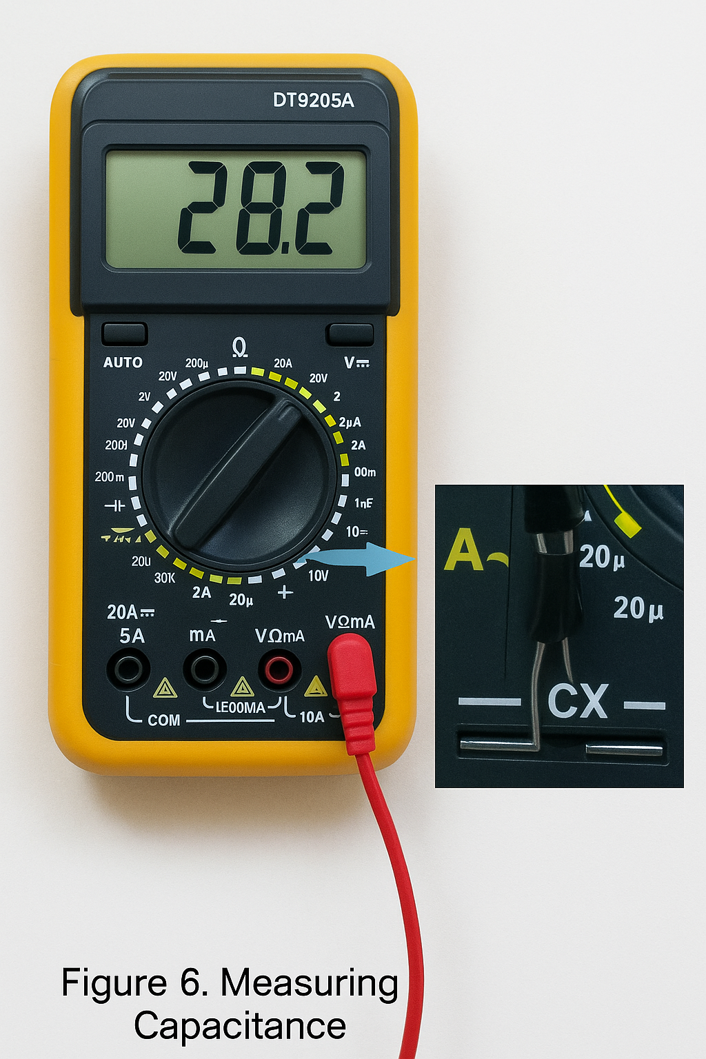
Steps: - Short the capacitor terminals to discharge it and ensure safety. - Set the function switch to the capacitance "F" range and select an appropriate range. - Insert the capacitor into the meter's CX terminal or dedicated capacitor socket and read the LCD.
Notes: - Capacitors must be discharged before measurement to avoid damaging the meter. - Discharge after measurement as well to avoid safety hazards. - The meter typically provides protection for the capacitance function, so polarity and charge/discharge behavior are not a concern during testing. - Use the dedicated capacitor test socket rather than the COM and V/Ω probe terminals. - Large capacitors may require some time for the reading to stabilize. - Unit conversions: 1 μF = 10^6 pF, 1 μF = 10^3 nF.
7. Diode Test
Steps: - Insert the red lead into VΩ and the black lead into COM. - Set the selector to the diode test position. - Place the red probe on the diode anode and the black probe on the cathode and read the display. - Reverse the probes: if the display shows "1" in this direction, the diode is not shorted and is likely good; if both directions show similar readings the diode may be damaged.
Notes: - A normal diode typically shows a forward voltage drop of about 0.6 V for silicon and about 0.2 V for germanium. The forward drop displayed indicates which probe is on the anode (red) and which is on the cathode (black).
8. Transistor Test
Steps: - Insert the red lead into VΩ and the black lead into COM. - Use diode-test methods to identify the base by comparing readings with a presumed base pin and the other two pins. - Determine transistor type (NPN or PNP). - Set the selector to the hFE (gain) range and use the dedicated hFE socket. Insert the transistor pins into the corresponding NPN or PNP positions for base (b), collector (c), and emitter (e). - Read the displayed beta (hFE) value.
Notes: - To identify base, assume one pin is base and measure forward voltage to the other two pins. If both measurements show about 0.7 V in one probe orientation and "1" in the reversed orientation, that pin is the base (for silicon). If not, try other pins. - To distinguish collector and emitter, insert the transistor into the hFE socket with the base in the correct hole and record the reading. Swap the other two pins and compare readings; the configuration with the higher hFE corresponds to the correct collector and emitter orientation.
Safety and General Notes
- If the approximate voltage or current is unknown, start at the highest range and reduce the range as appropriate.
- After measurements, set the range switch to the highest voltage range and turn the meter off.
- At full-scale overrange the meter displays "1" in the highest digit and other digits disappear; select a higher range in that case.
- When measuring voltage place the meter in parallel with the circuit; when measuring current place the meter in series. For DC measurements pay attention to polarity.
- If you use the AC voltage range to measure DC voltage or vice versa, the display may show "000" or unstable lower-digit readings.
- Do not change ranges while measuring high voltage (above 220 V) or large currents (above 0.5 A) to avoid arcing and contact damage.
- When the meter battery is low a battery symbol appears on the LCD. Low battery may cause measured values to read higher than actual; replace the battery when low.


