Summary
Below are the issues encountered when measuring signal amplitude and an analysis of their causes.
Problem description
When measuring a single-board signal with a multimeter, a discrepancy was observed between the measured voltage and the expected DC level. The measurement setup is shown below.
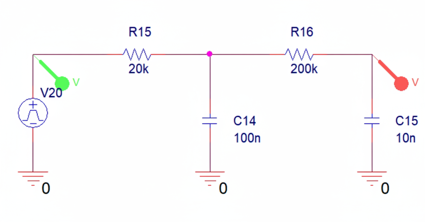
The RC low-pass filter is intended to remove high-order harmonics from a 5 kHz PWM signal and leave the DC component, because the microcontroller has no DAC peripheral and PWM is used to emulate an analog output. For a 3.3 V microcontroller with 50% duty cycle, the expected DC after filtering is 1.65 V. Simulation shows the PWM (green) and the filtered DC (red) after a second-order RC filter.
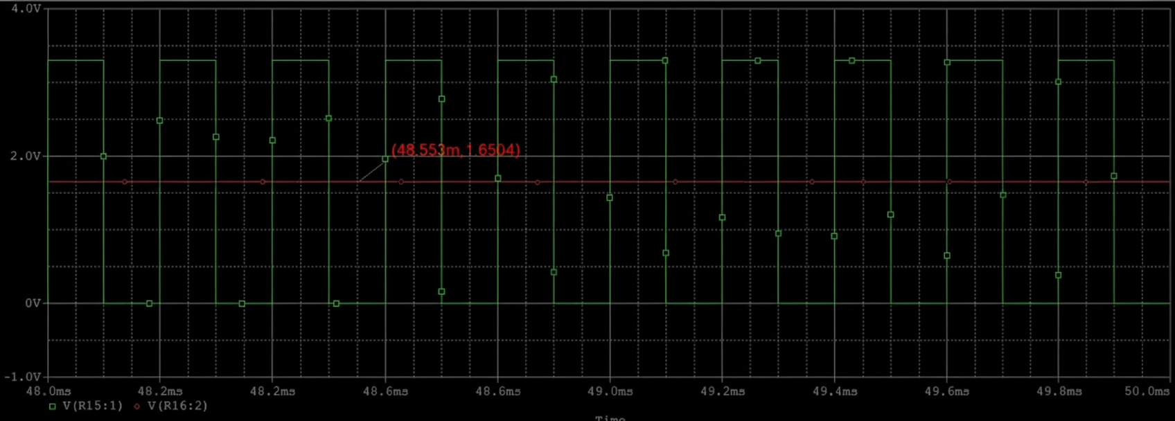
However, measurements with a handheld multimeter consistently read lower than the theoretical 1.65 V (about 1.61 V). Changing the PWM duty cycle also produced measured values that were lower than expected. It was unclear whether the filter was at fault.
Analysis
A senior technician identified the cause: the output impedance of the signal source (about 20 kΩ + 200 kΩ in this case) forms a voltage divider with the input impedance of the measuring instrument. A typical handheld multimeter has an input impedance of 10 MΩ, which in most cases is high enough, but with unusually large source impedance it can still create measurable loading. An oscilloscope probe can produce an even lower reading because a standard 1x probe or improperly compensated probe has about 1 MΩ input impedance.
Verification
Using a bench multimeter with higher input impedance (Agilent 34410A, which defaults to 10 MΩ and can be configured to 10 GΩ) produced a measured voltage equal to the theoretical 1.65 V after the second-order RC filter.
Conclusion
The input impedance of the measurement instrument can affect measured values. If the signal source has a relatively high output impedance, use a measurement device with sufficiently high input impedance to avoid significant voltage-divider loading and resulting measurement error. In most practical cases the source impedance is low and a 10 MΩ handheld multimeter is adequate; this example represents a less common situation where loading caused a noticeable error.


