Introduction
Geometrical optics is the foundation of optical design. Effective optical design requires understanding the imaging principles of various optical instruments. This article summarizes the imaging principles of several common optical instruments.
Optical Imaging
Optical imaging reproduces information about objects by means of refraction, reflection, and related effects. Imaging is one of the core problems studied in geometrical optics.
Real and Virtual Images and Objects
1. Objects and images both consist of a series of points; object points and image points correspond one-to-one.
2. A real object or image means that light actually originates from or passes through that point. A virtual object or image is a perceptual effect caused by straight-line propagation of light; no light actually passes through that point.
3. Object and image type is relative, and conversion between real and virtual can occur.
Equal Optical Path Surfaces and Ideal Imaging
Ideal imaging requires invariance of concentric light bundles and similarity between object and image across the entire object-image correspondence. Spatial positions of points must map one-to-one, and corresponding object-image point colors must match. An imaging system should produce no distortion, spherical aberration, chromatic aberration, or other aberrations. An ideal lens group is a necessary condition for perfect imaging.
Projectors
Key Parameters of Projectors
Brightness: Typical home units are about 2000–3000 ANSI lumens.
Native resolution: the actual physical resolution of the imaging panel.
Contrast ratio: the luminance difference between the brightest white and the darkest black in bright and dark regions (human perception is typically near 2000:1).
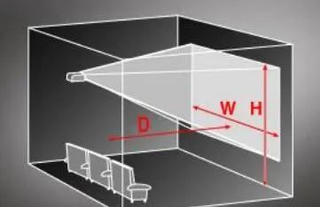
Throw ratio: projection distance D divided by image width W. A smaller throw ratio means a larger image at the same distance. Throw ratio is used to calculate optimal projector-to-screen relationships. Typical throw ratios are 1.5–1.9. Ratios below 1 are considered short throw; below 0.6 are ultra-short throw. Screen sizes are usually specified by diagonal inches and can be converted for different aspect ratios.
Screen Selection
Glass-bead screens have a coating with optical glass beads. They produce a pronounced sense of focus and vividness, have high gain and narrow viewing angles. Their main characteristic is retro-reflectivity: reflected light tends to return along the incident direction, which increases gain and provides partial light collection.
White plastic screens use a coarse white surface material without special surface treatment. They reproduce the projector's output without modification, with low gain, wide viewing angles, and natural color reproduction.
Cameras
Box Camera: Simplest Camera Structure
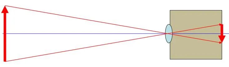
Features: no reflex mirror; direct view and focus.
Drawback: earlier box cameras had slow focusing. Modern digital mirrorless cameras can achieve autofocus times below 0.06 seconds (for example, Sony a6000).
Twin-Lens Reflex (TLR)
Features: two lenses. The upper lens is fixed with a mirror for viewing and focusing and is mechanically linked to the lower lens. The lower lens projects the image onto film.
Drawbacks: relatively large size, inconvenient handling, and lens changes require replacing both lenses together.
Single-Lens Reflex (SLR)
Features: pentaprism and reflex mirror solve the "what you see is what you get" problem for viewfinding.
Drawbacks: moving reflex mirror increases camera volume; mirror slap and mechanical switching time can affect performance.
Lens Focal Length and Field of View
Focal length determines image size: longer focal length yields a larger image on a fixed-size sensor but narrows the field of view. A short focal length produces a wide field of view, hence the term "wide-angle" lens. Conversely, long focal lengths produce narrow fields of view and are called "telephoto" lenses.
Focal Length and Longitudinal Interval
Short focal length corresponds to a larger longitudinal interval; long focal length corresponds to a smaller longitudinal interval.
Field of View and Image Field
A standard lens focal length is roughly equal to the diagonal of the camera's imaging plane. When a lens focal length approaches the imaging plane diagonal, it is considered the standard focal length for that format. A standard focal length lens has an angle of view around 50° and a focal length typically between 45 and 55 mm. Its perspective resembles that perceived by the human eye and yields natural-looking images.
Shutter and Aperture
The aperture limits the cone of rays that form an image and restricts the range of off-axis object points relative to the optical axis. An aperture is required for approximate imaging in spherical lens groups.
Aperture diaphragm (effective aperture): the diaphragm that determines the cone of rays on the optical axis for an object point. The angles of the object and image cones limited by the aperture diaphragm are called the entrance and exit aperture angles respectively. The aperture relates to paraxial conditions for on-axis object points.
Entrance and exit pupils: conjugates of the aperture diaphragm on the object and image sides, respectively, collectively referred to as the pupils.
Apertures and pupils are defined for specific conjugate object-image points; different conjugate pairs can have different apertures and pupils.
Principal ray: in a conjugate object-image bundle, the ray that is conjugate with the center rays through the entrance and exit pupils.
Field diaphragm: the diaphragm that determines whether principal rays from off-axis object points can pass through the optical system. The angles between the principal ray and the optical axis on the object and image sides are the entrance and exit field angles. The field diaphragm sets paraxial conditions for off-axis object points.
Entrance window and exit window: conjugates of the field diaphragm on the object and image sides.
Vignetting: as an object point moves away from the optical axis, participating rays in imaging decrease, causing the image to darken. If the entrance window lies in the object plane, vignetting will not appear.
Depth of Field and Depth of Focus
Depth of field controls how much foreground and background are acceptably sharp. A shallow depth of field blurs foreground and background, while a deep depth of field keeps more of the scene in focus.
Factors Affecting Depth of Field
Depth of field is influenced by aperture size, focal length, subject distance, and acceptable circle of confusion. Reducing aperture (larger f-number) increases depth of field; increasing focal length decreases depth of field at the same subject framing and aperture.
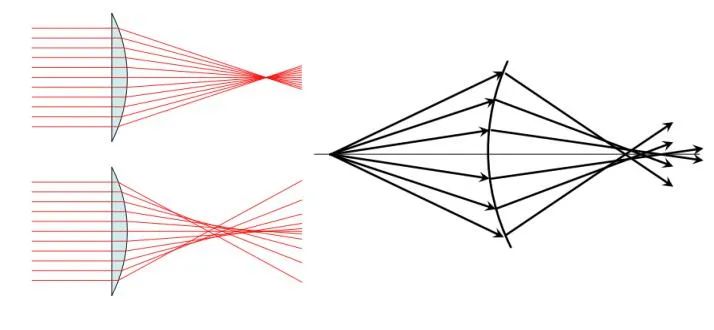
Spherical Aberration
Rays from an on-axis object point at large aperture do not converge to a single point, causing spherical aberration.
Coma
For off-axis object points, wide bundles of rays no longer meet at a point and form comet-shaped spots called coma.
Astigmatism
For off-axis object points, horizontal and vertical rays focus in different planes. The two focal lines are perpendicular to each other; this effect is astigmatism. The best position for film or sensor is the circle of least confusion.
Field Curvature
Field curvature (Petzval curvature) causes the best-focus surface to be curved rather than a plane.
Distortion
Distortion occurs when transverse magnification varies with distance from the optical axis, so shapes in the image plane are not geometrically proportional to the object. Unlike spherical aberration, coma, and astigmatism, distortion preserves the concentricity of light bundles and therefore does not reduce image sharpness.
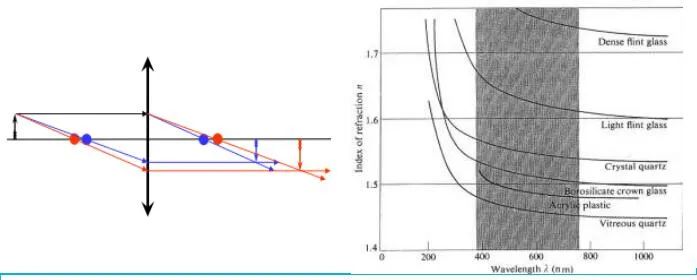
Chromatic Aberration
Because refractive index varies with wavelength, white light forms images with different positions and sizes for different colors. Chromatic aberration is classified as axial (longitudinal) chromatic aberration and transverse (lateral) chromatic aberration.
Magnifying Glass and Eyepiece
A magnifying glass acts as an eyepiece, producing a magnified virtual image for eye observation. Typically the object is placed inside the object-side focal plane and the image distance is near the comfortable viewing distance.
Eyepieces used in optical instruments serve a similar function to a magnifying glass, forming a virtual image near the normal viewing distance so the eye can observe directly. Eyepieces are usually paired with objectives and one design goal is to eliminate visual chromatic aberration.
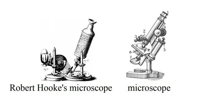
Microscopes
Microscopes are high-magnification optical instruments composed of objective lens groups and eyepiece groups.
Eyepiece Types and Markings
Eyepiece types include Huygens (H), Ramsden (R), Kepler (K), etc. Magnifications are typically 5×, 10×, etc. The apparent field diameter may be specified in millimeters. For example, "10×/18" indicates 10× magnification and an 18 mm field diameter.
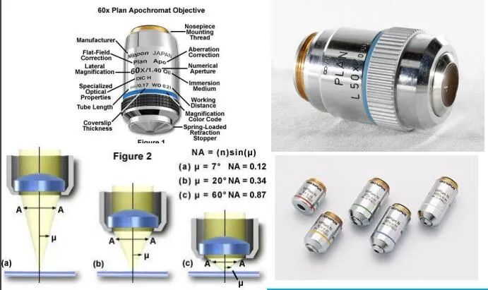
Objective Markings and Parameters
Objective color bands and numerical aperture indicate magnification and the light-gathering ability of the objective.
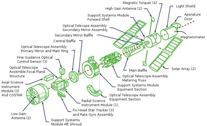
Telescopes
Telescopes are used to observe distant objects by increasing the angular size of objects as seen by the eye. They form a reduced real image at a near location, which is then magnified by the eyepiece.
Hubble Space Telescope Diagram