01 Background
It started from one question: can a 1X passive probe be treated as a coaxial cable and used to match a 50 ohm or 75 ohm system? Experienced engineers immediately answer no, because even a 1X probe has a significant resistor in series. I had a scrapped probe on hand and measured it with a multimeter; the center conductor measured over 300 ohms, while the outer conductor was a few tenths of an ohm. Such a "coax" clearly cannot be used to match a 50 ohm or 75 ohm system.
The question seemed answered, but it deepened my curiosity: why is there such a large series resistor in the probe, and why is the bandwidth of a 1X probe so much lower than a 10X probe?
02 Disassembly and internal components
Passive probes are not easy to disassemble. The plastic housing is hard and molded; even after removing the plastic there is a metal sleeve that is hard to pry off. After much effort and a few minor injuries, I managed to extract the internals:
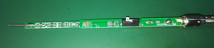
Inside the passive probe: a probe tip, a small PCB, several resistors and capacitors, a single-pole double-throw switch, and a short coaxial cable.
The circuit looks like this:
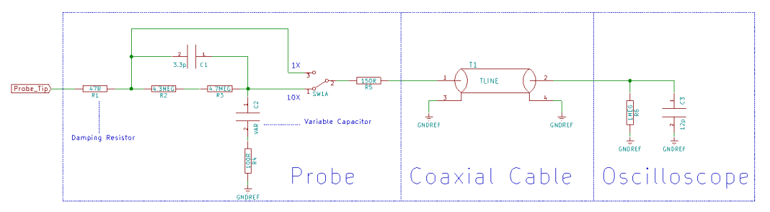
03 Damping resistor on the probe
Indeed, the probe has a sizable series resistor. Why is it there? A simple model and simulation help explain:
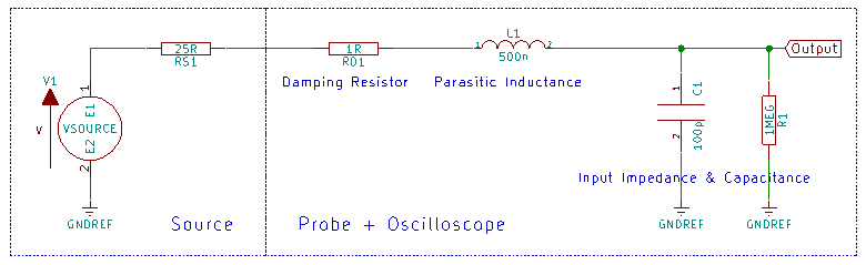
The oscilloscope measurement system model: RS1 represents the source internal resistance, taken here as an empirical 25 ohms; RD1 is the probe input damping resistor, which will be swept in the simulation; L1 is the probe cable parasitic inductance, taken as 500 nH; C1 is the sum of the probe cable parasitic capacitance and the oscilloscope input capacitance, taken as 100 pF by experience; R1 is the oscilloscope input resistance, 1 MΩ.
The damping resistor mainly counteracts peaks in the frequency response caused by the probe's parasitic inductance. If the damping resistor is too small, the peak is large and the time-domain waveform shows significant overshoot. If the damping resistor is too large, the system bandwidth is reduced. In practice, the resistor value is chosen as a compromise based on the probe and oscilloscope characteristics.
04 Why 10X probes have higher bandwidth than 1X probes
From the previous section, because of parasitic capacitance, inductance, and the damping resistor, the 1X probe system bandwidth is relatively low. A 10X probe achieves higher bandwidth by adding an attenuation network with compensation. A simplified system model is shown here:
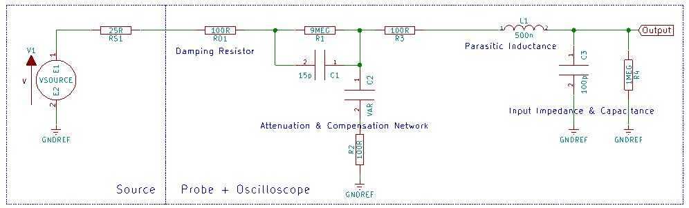
In this model RD1 is set to 100 ohms, giving about 17 MHz bandwidth in 1X mode. The damping resistor in series with the probe cable parasitic inductance is followed by an attenuation and compensation network; C2 is an adjustable capacitor (the probe compensation trimmer). By adjusting C1, C2, R2, and R3 appropriately, a more ideal system frequency response can be achieved.
Real probes are more complex than this model. Users of high-bandwidth passive probes may notice, besides the low-frequency compensation point (e.g., the 1 kHz square wave trimmer represented by C2), one or two additional high-frequency compensation adjustments, possibly implemented with R2 and R3, to tune high-frequency overshoot.
05 Not an ordinary coaxial cable
With the probe internals explored, return to the original question: can a 1X passive probe be used as a coaxial cable to match a 50 ohm or 75 ohm system? No, because the probe includes a large damping resistor in series. If I cut off the probe tip and try to use the remaining length of coaxial cable to match a 50 ohm or 75 ohm system, would that work? Few people answer that correctly.
I measured the removed coax on a VNA to see what it actually is.
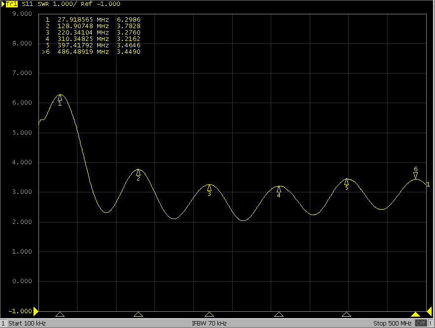
Coax S11 parameter
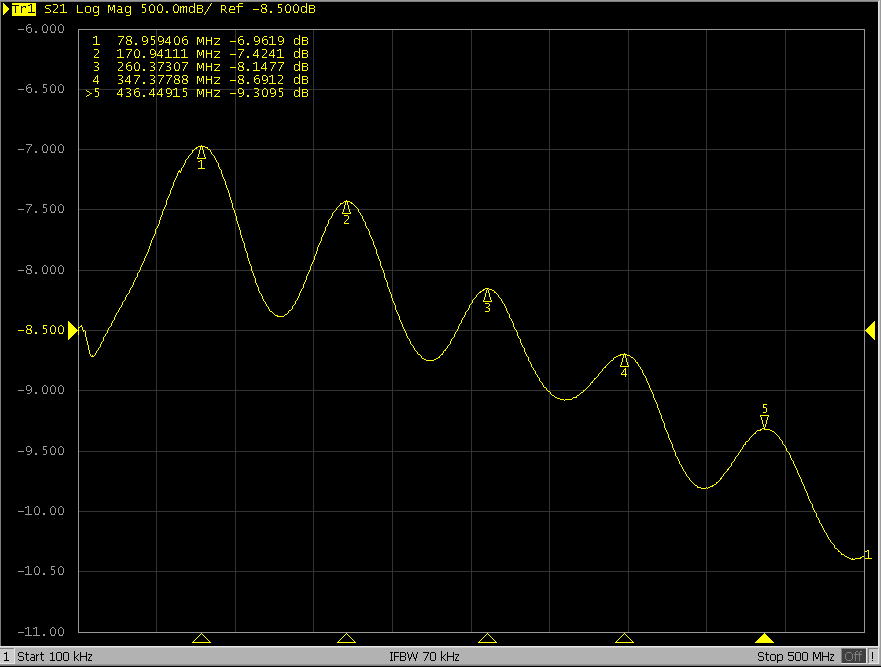
Coax S21 parameter
What the...? It does not behave like a normal coaxial cable at all. I repeated the measurements many times, ruled out VNA faults, calibration issues, test method errors, and a broken cable... the result is really this bad.
Attentive readers may recall I measured the probe center conductor with a multimeter and saw more than 300 ohms, while the simplified circuit implied the damping resistor should be under 200 ohms. Where did the missing 100+ ohms go? It was in the coaxial cable. Measured with a multimeter, a roughly 1 m length of that cable had nearly 180 ohms resistance in the center conductor.
Such high resistance does not mean the cable is damaged; it exists for a reason. A TDR shows the behavior clearly.
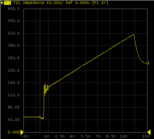
Coax TDR test
The trace is an inclined line, indicating impedance is continuously distributed along the cable. This is similar to a tapered impedance, but it is different from a typical tapered feed: the insertion loss is especially high because a significant resistive component is present.
In a system composed of the source under test, a passive probe, and an oscilloscope, the source impedance is unknown while the load is 1 MΩ. How should this probe transmission line be matched to the system? One simple approach is not to match and instead use a high-loss transmission line to reduce reflections. That is a crude but effective solution. (I am not deeply experienced in RF; readers are welcome to point out any inaccuracies.)


