The concept of measurement is straightforward, but implementing a system requires resolving many practical details, including how to configure a laser-based 3D triangulation system and how to set laser line parameters.
Principle
In a laser-based triangulation system, a narrow light stripe is projected onto a 3D surface. From an observation angle offset from the projector, the stripe appears distorted (see Figure 1). By analyzing the shape of that stripe in the image, the surface geometry of the object can be reconstructed with high precision.
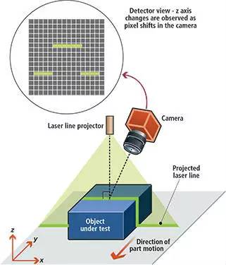
Figure 1: A distorted laser line as seen from an angle offset from the projector. This distortion is used to derive the measured object dimensions.
System components
A 3D triangulation system typically consists of four key elements: a camera, a structured laser source that projects the line, a mechanical structure to move the object or the camera/laser assembly through the field of view, and image-processing software capable of converting pixel displacements into height differences with high accuracy.
Triangulation geometries
There are several implementations of laser line projection optics, each with distinct advantages and disadvantages. Figure 2 shows four common geometric configurations.
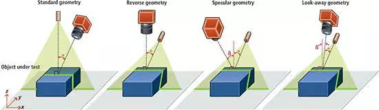
Figure 2: Four common machine vision configurations based on 3D triangulation.
In the commonly used standard geometry, the laser line is projected perpendicular to the nominal measurement (X,Y) plane. A key feature of this geometry is that height variations along the projected line do not change the line's Y coordinate in the camera image. This simplifies the calculations required to derive the surface shape, enabling faster and more accurate system setup and simplifying calibration during installation.
One drawback of the standard geometry is that the camera views the object from a non-perpendicular angle, which increases depth-of-field requirements: the system must remain focused across height variations of the object. This also implies that, as distance (from lens to object) varies with height, the lens needs higher magnification. Therefore, calibration of the object is necessary for the system to produce accurate measurements.
Beam uniformity and definitions
Two common issues arise when characterizing beam brightness across the laser line. First, averaging brightness over the entire beam length masks absolute power variations along the beam. Second, such averaging ignores beam-edge regions, which often have the worst performance.
To address these shortcomings, Coherent has defined strict uniformity standards that effectively cover the full beam. Specifically, the beam edge is defined as the location where power drops to 80% of the normalized peak. The average brightness across the beam must cover this region and the absolute power within it must not fall below 75% of the peak value (see Figure 3). This is a stricter uniformity requirement than simply specifying an average over a designated area of the beam.
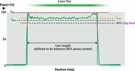
Figure 3: Brightness integral versus laser line position, identifying peak brightness (Imax), minimum brightness (IMin), average brightness (IAvg), and the 80% peak power location.
This stricter definition provides two practical advantages for system developers. First, for existing equipment and CDRH safety classifications, higher projected power directly improves the signal-to-noise ratio (SNR) in the captured images, yielding faster and more accurate vision systems. This is because CDRH classifications are based on peak power without regard to where the peak occurs within the beam. If the peak is at the beam edge while the center is relatively weak, the safety classification is still based on the higher peak value.
Second, complying with this specification increases unit-to-unit uniformity, which simplifies calibration and helps maintain system stability for integrators. Because the specification defines an absolute lower limit on brightness, it constrains the total variation that can appear within the beam more tightly than a simple average-based criterion.
Laser line width
Even with ideal manufacturing, the focused line width and length change with distance between the laser and the measured object. The magnitude of this change depends heavily on how the laser source is used to generate the line, so the choice of projection optics significantly affects system performance.
Most line projectors are based on diode lasers. Diode lasers have a relatively large source size and typically exhibit lower divergence in one direction (the slow axis) than in the orthogonal direction (the fast axis).
This is an inherent property of diode lasers: the emitting facet is longer in one dimension than the other. Line-projection optics can be configured to extend either the fast axis or the slow axis into the long dimension of the line. The diffraction effects resulting from that choice will influence the laser line performance in three important ways (see Figure 4).
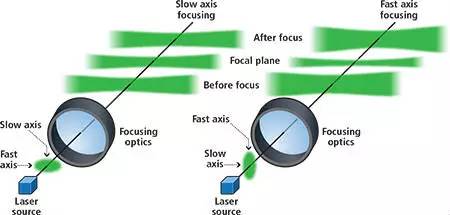
Figure 4: Using the slow axis as the focused line-width direction yields a wider beam with larger depth of field and a less pronounced "bow tie" effect.
First, a smaller line width at the focus can be achieved by directing the input beam so the fast axis defines the beam width while the slow axis defines its length. A narrower line width provides higher resolution and greater power density, allowing the system to resolve finer surface height variations.
However, diffraction causes a highly focused narrow line to diverge more rapidly outside the focal region than a wider line. Therefore, obtaining a narrower focused line (and thus higher resolution) necessarily reduces the usable depth of field; beyond a certain distance the line width will broaden to unacceptable levels.
Finally, there is a notable effect when a planar object is perpendicular to the laser beam path: the beam edges reach the object at a slightly greater distance than the beam center because of divergence. This makes the edges of the line slightly wider than the center, assuming the focus is at the line center. This phenomenon is often called the "bow tie" effect. It is more pronounced for beams that diverge more quickly.
Line straightness
Another important parameter is line straightness. In practice, projected laser lines are rarely perfectly straight. The most common distortion is a bow shape; occasionally a slight "S" shape appears. Bowing is typically caused by the input beam entering the beam-shaping optics at a non-normal incidence angle.
Because line straightness depends on optical alignment, it can change over time due to transmission between optical units. Line straightness must be taken into account during calibration to achieve accurate measurements.
Conclusion
Laser triangulation systems that use line projectors can offer higher speed and accuracy than many other 3D vision techniques, but system simplicity can be misleading. Performance depends on several system parameters, and some vendors handle these parameters ambiguously. Understanding how to define key system parameters is therefore important to achieve a triangulation system that meets the intended performance and cost targets.


