Measuring output voltage ripple is a quick way to evaluate the performance of modern power converters and low-dropout regulators (LDOs). Different measurement techniques can produce differing ripple evaluations, so obtaining an accurate ripple value is critical. This design note explains practical methods for measuring output voltage ripple to verify the performance of DC-DC power converters. First, the note briefly explains voltage ripple, then compares the waveforms from the traditional long-loop measurement and the tip-and-barrel measurement. Finally, three practical measurement tips and a conclusion are provided.
1. Introduction
Modern electronic applications commonly include embedded computing and wireless connectivity. These circuits often generate high-current pulses and heavy dynamic load behavior while requiring low input voltage ripple. New generations of DC-DC converters therefore need faster transient response and the ability to maintain a stable output under fast-changing loads. LDOs should provide comparable or better output ripple. To evaluate converter output ripple, it is important to use measurement methods that avoid coupling extra noise into the measured waveform.
Different measurement setups can capture different amounts of noise, which can distort the observed ripple and lead to an incorrect assessment of converter performance. Figure 1 shows how noise can combine with the actual output ripple to increase the measured ripple amplitude. A common measurement error when using a traditional setup is connecting a standard USB adapter directly to the output, which can introduce additional noise. The next section explains why inaccurate measurements occur and how to address the problem.
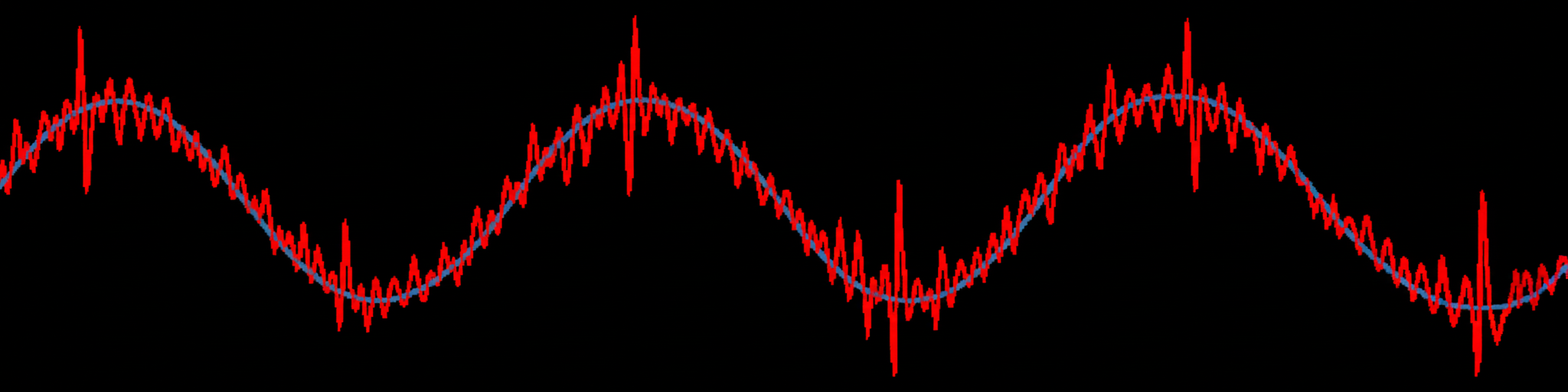
Figure 1: Measured output ripple combined with added noise
2. Measuring Output Voltage Ripple
Traditional connections with large measurement loops cannot accurately capture the ripple of switching converters because long ground leads and probe tip connectors can form a loop antenna that collects ambient noise. That noise superimposes on the output waveform and makes the measurements incorrect.
To measure the actual output ripple, the measurement loop must be minimized. The tip-and-barrel measurement technique is one of the recommended accurate methods. It is easy to implement and is well known for producing a small measurement loop that reduces noise pickup.
Note that the measurement point can also affect the output ripple result. Choose a measurement point that minimizes the noise-collecting loop. A typical measurement point is directly across the output capacitor solder pads. The closer the probe connection is to the capacitor, the less noise is collected during the measurement. Figure 2 shows the tip-and-barrel method applied at the output capacitor compared with the traditional method at the output terminal. The tip-and-barrel region forms a much smaller noise-collecting loop, which explains why the traditional method often shows a noisy waveform.
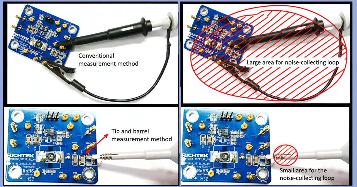
Figure 2: Comparison of traditional method and tip-and-barrel method
Figure 3 shows the comparison between the traditional long-loop method at the output and the tip-and-barrel method on the capacitor using different oscilloscope bandwidth settings. The results show that the traditional long-loop method produces waveforms with substantial noise and exaggerated ripple, while the tip-and-barrel method yields a much cleaner output waveform and enables an accurate ripple measurement.
3. Practical Tips
3.1 Minimize the measurement loop
The measurement loop area plays a major role in noise pickup when measuring DC-DC converter output ripple. Always minimize the loop area. The tip-and-barrel method reduces the impact of noise on the measured ripple values.
3.2 Choose an appropriate measurement point
Ensure the measurement loop is as small as possible. Typically, choose a point close to the output capacitor pads and ensure the connection impedance is low. The closer the measurement point is to the capacitor, the less noise will be collected during measurement.
3.3 Set the sampling bandwidth
Different applications have different sensitivity to noise caused by converter output ripple. For noise-sensitive applications, such as high-resolution analog-to-digital converters (ADCs) or audio applications, measure output ripple at full bandwidth. For noise-tolerant applications, a 20 MHz bandwidth setting may be acceptable. Note that full-bandwidth measurements are still required to obtain an accurate representation of the total output ripple.
4. Conclusion
The tip-and-barrel method minimizes measurement-induced noise when measuring DC-DC converter output voltage ripple and is straightforward to implement for accurate results. Combined with an appropriate sampling bandwidth and a measurement point close to the output capacitor, accurate ripple measurements are readily achievable. This approach is suitable for verifying the performance of most fast DC-DC converters.


