Overview
DC current test instruments are few and expensive. In electronics, the two primary parameters are voltage and current.
PPK2 Functionality
Power Profiler Kit II (PPK2) is an easy-to-use current measurement and power optimization tool for embedded applications. It supports power mode and ammeter mode.
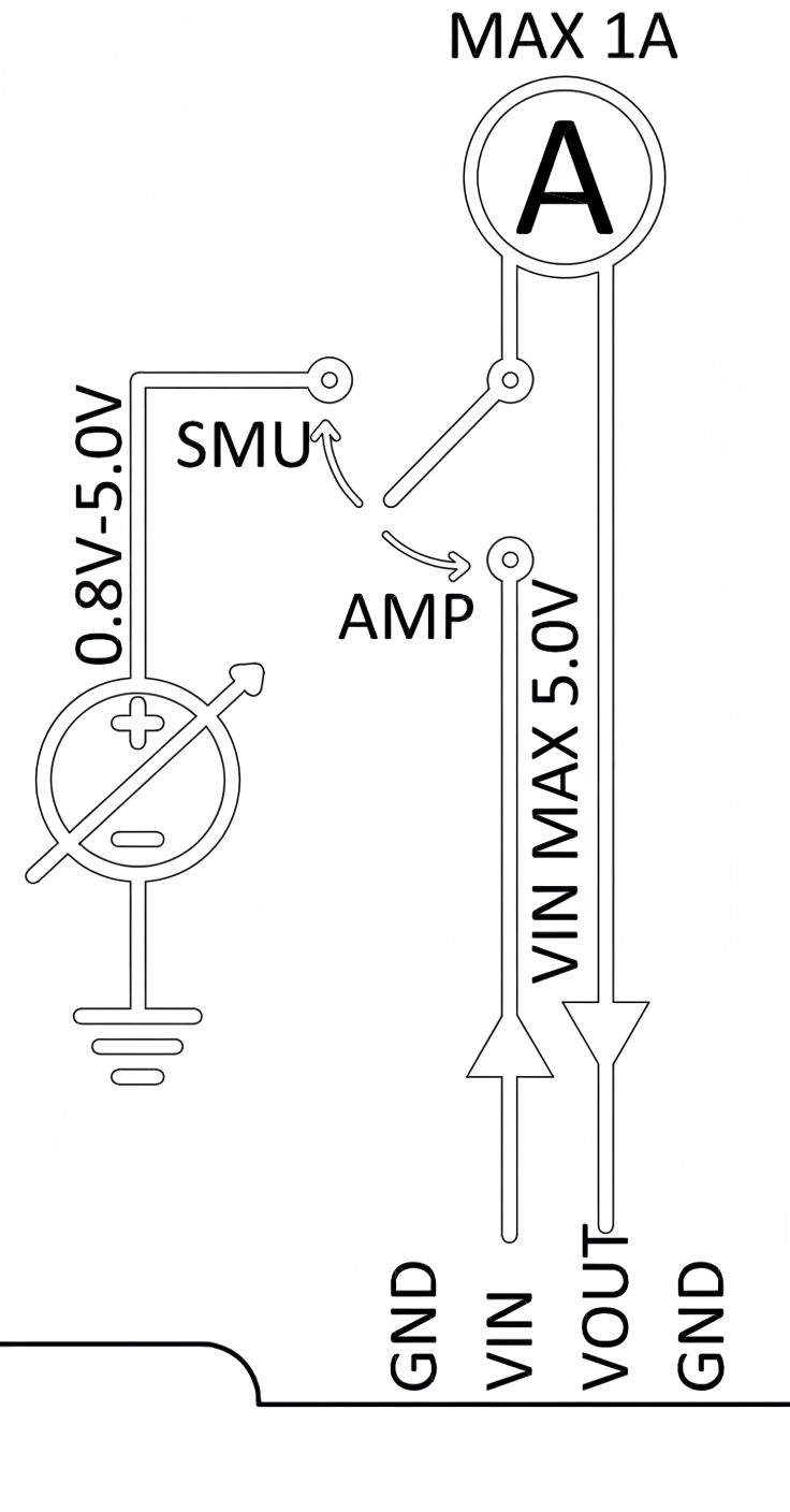
In power mode, the PPK2 can both supply power and measure the current of an external device under test (DUT). The onboard regulator in power mode can provide up to a 1 A peak current.
Both modes support VCC levels from 0.8 V to 5 V. In ammeter mode, the DUT is powered by an external supply.
The PPK2 uses an advanced analog measurement unit with a high dynamic input range to accurately measure currents common in embedded systems, from 200 nA up to 1 A. It can measure from shutdown currents up to the maximum current of Nordic or external hardware.
Measurement resolution varies between 100 nA and 1 mA depending on the selected range. The PPK2 also offers sufficient time resolution to capture peaks, achieved via a 100 ksps current sampling rate.
Diagrams and Board Images
Another diagram
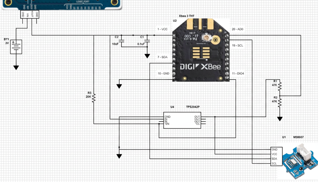
Example: Zigbee IoT Sensor Node
The project consists of a Zigbee node, an environmental sensor, and a single battery. The goal is to measure power consumption data.
Battery Capacity Estimation
Battery life is estimated by dividing the nominal battery capacity by the average current drawn by the load. Battery capacity is usually expressed in ampere-hours (Ah) or milliampere-hours (mAh). The average current is determined by averaging currents across sleep and wake cycles.
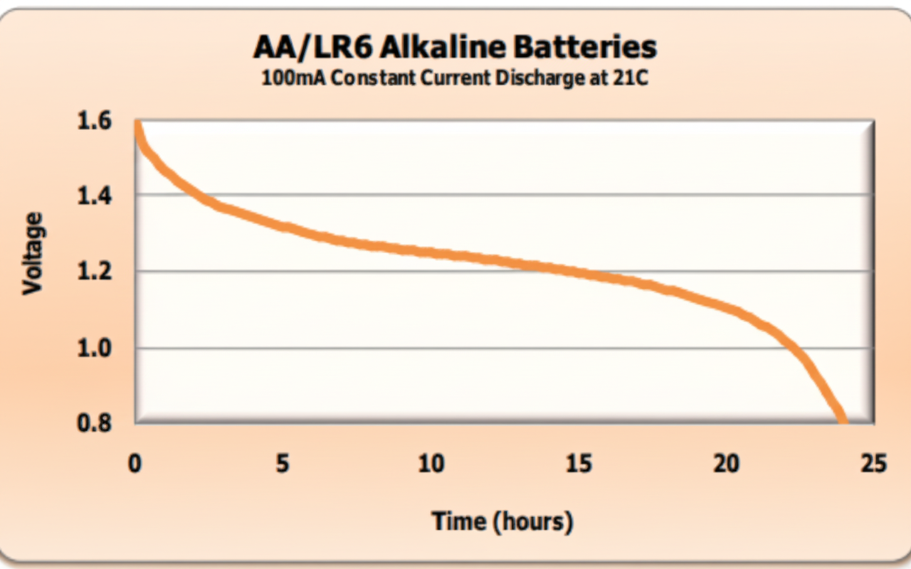
For example, an AA/LR6 alkaline cell discharged at 100 mA down to a 0.8 V cutoff yields approximately 2500 mAh, calculated as 100 mA × 25 hours.
The minimum supply voltage for the IoT sensor used in this project is 2.1 V (2 × 1.05 V). Therefore, with a 100 mA draw down to a 1.05 V cutoff per cell, the AA/LR6 cutoff capacity is roughly 2100 mAh (100 mA × 21 hours).
Measured Currents
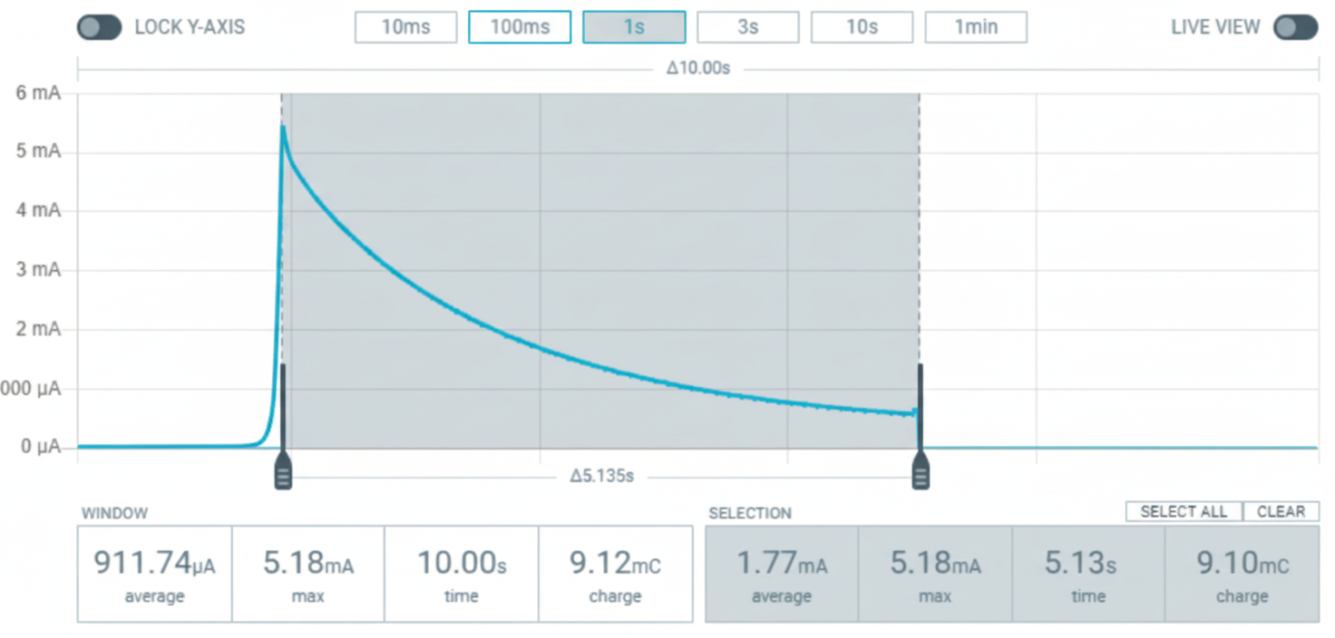
Average current during wake
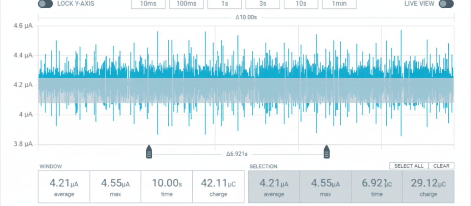
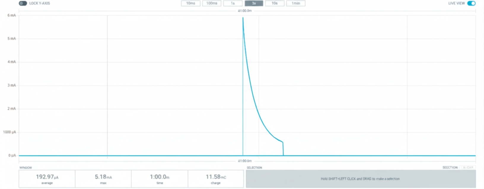
Average current during sleep
The measured average current during wake was 1.77 mA over a 5.135 s duration. The measured average current during sleep was 4.21 μA over 60 s. The full wake/sleep cycle is approximately 65 s. The computed overall average current is about 0.142 mA. Based on a 2100 mAh battery capacity (2.1 V cutoff), the sensor battery life is estimated to be about 1 year and 8 months.
Connections and Measurements
Current must be placed in series with the DUT
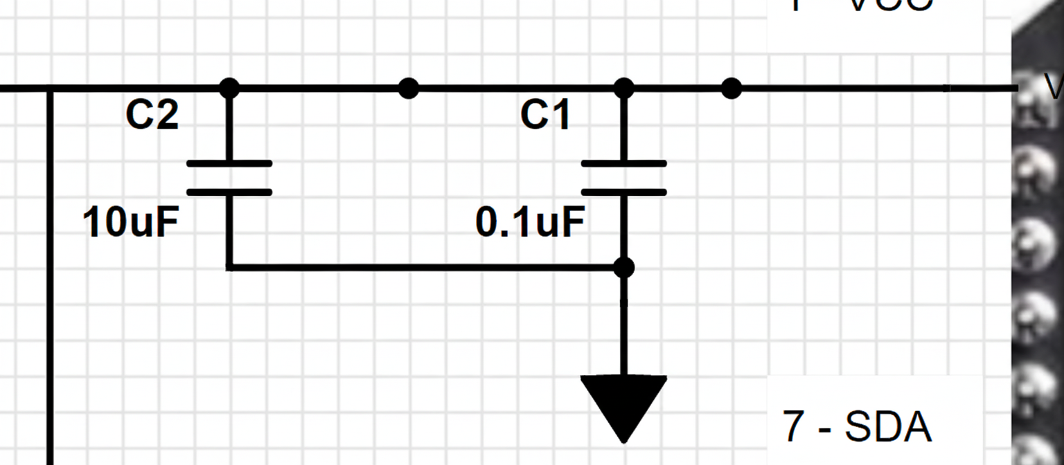
Remember to filter the input
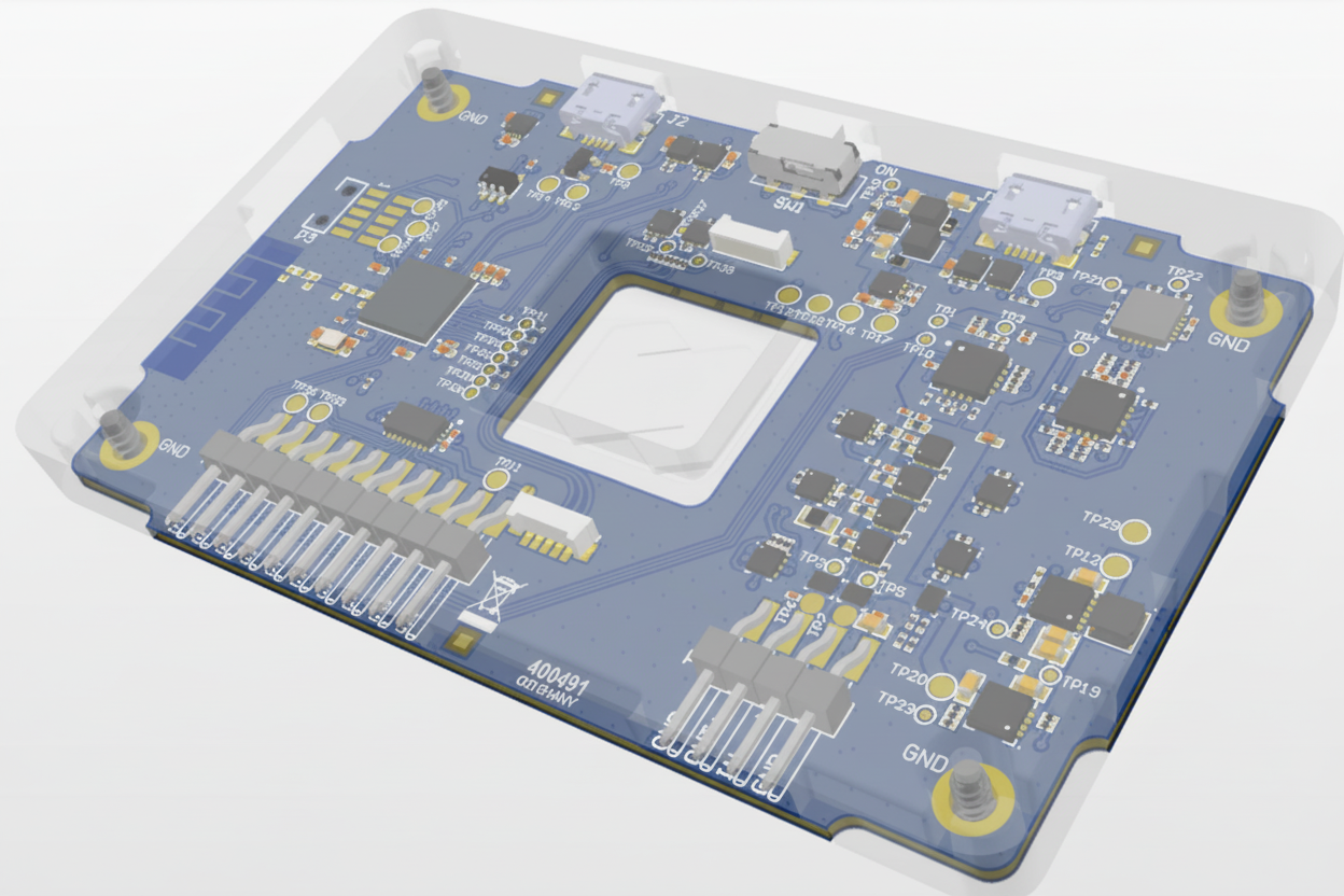
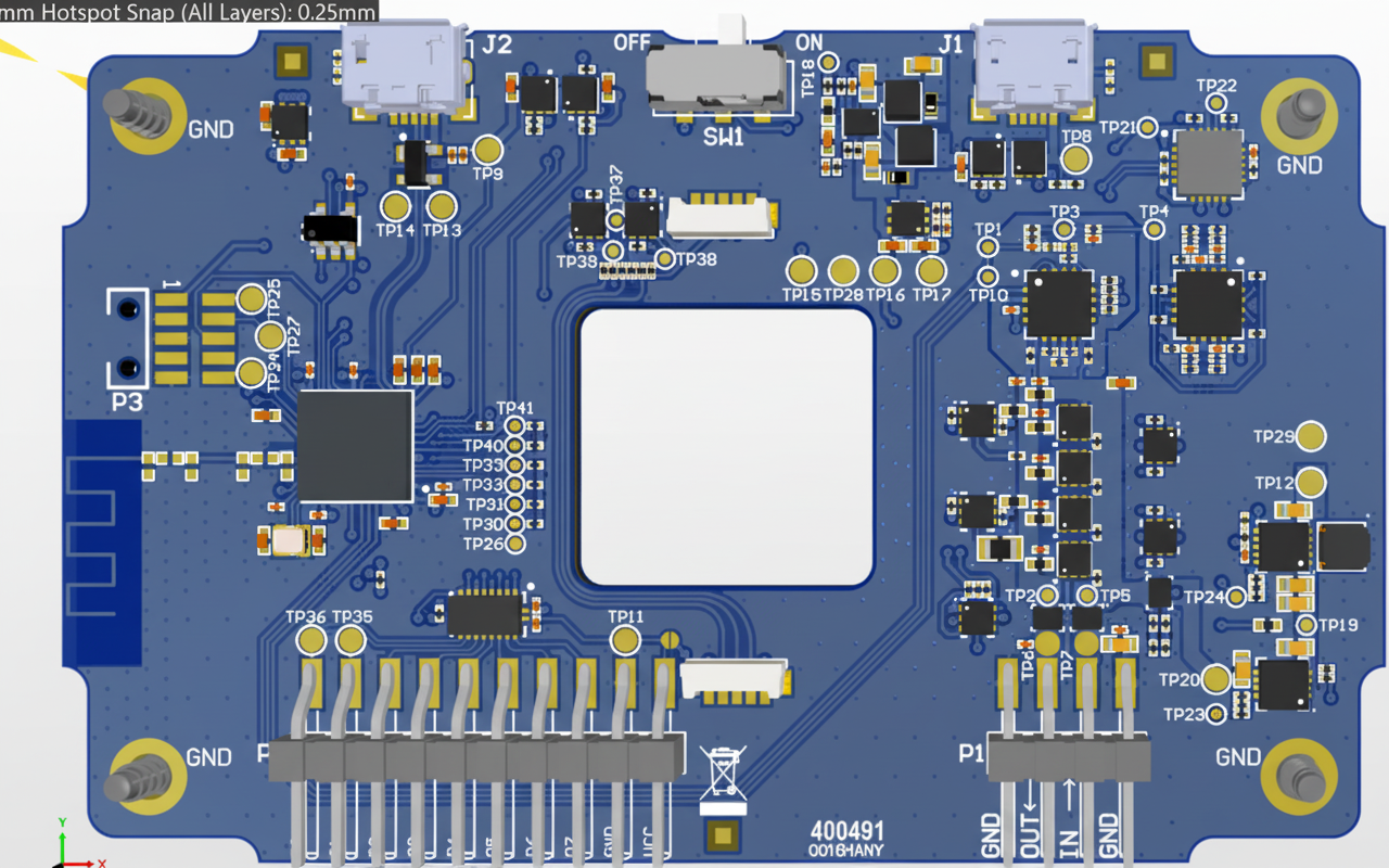
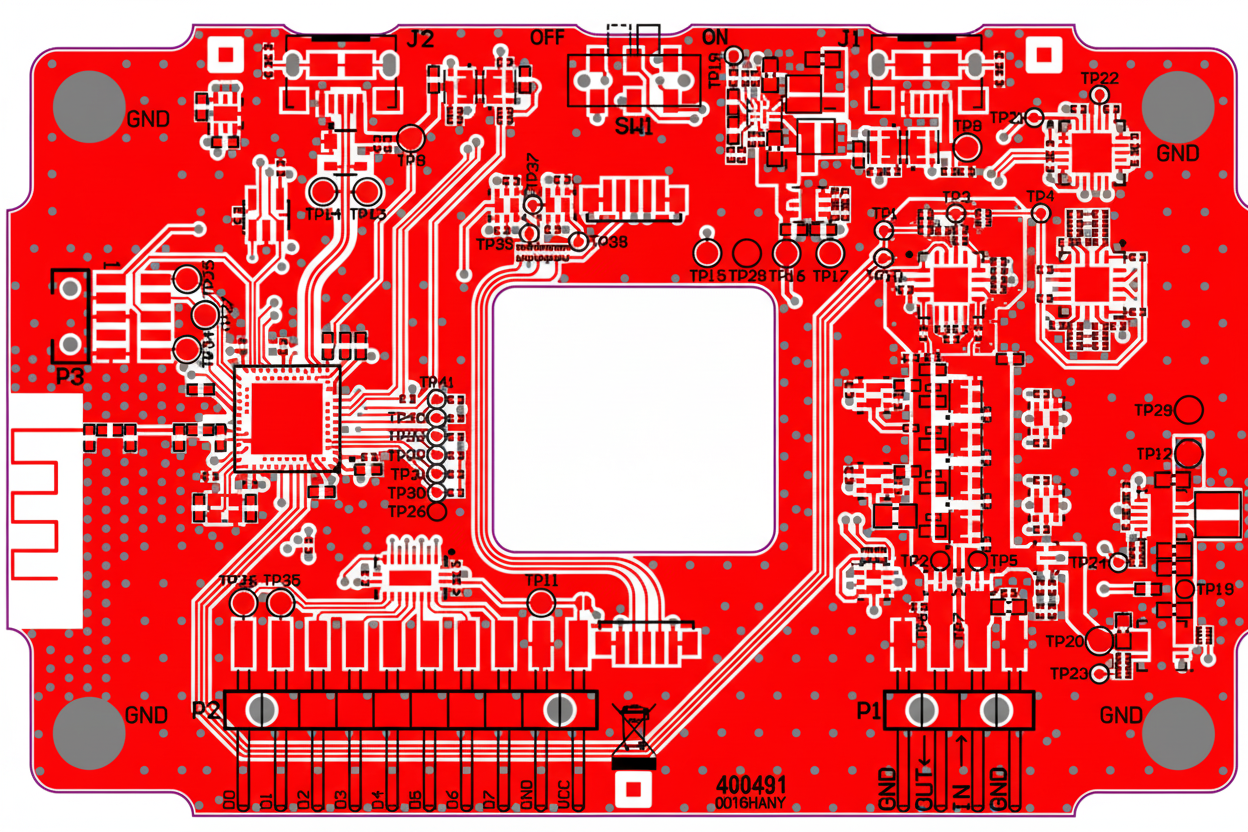
PCB and Layout
The PCB layout appears neat. The front of the PCB is shown below. The design uses a 4-layer board and the chip employs semi-buried vias.
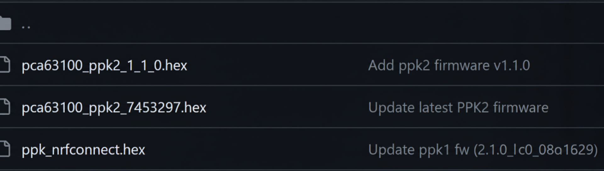
Firmware and Small-Current Tester
Firmware images and small-current tester photos are shown below.

Connectors and Probing Options
- 5.08 mm pitch thumb/screw terminal: convenient for input but can be mounted on the output.
- Gold banana jack / screw terminal: available on input and output.
- Slim banana jack terminals: available on input and output.
- Header pins can be soldered at different points to facilitate clip DMM probing.
- Dedicated pinhole output for low-inductance oscilloscope probing.


