Meaning of Phase Noise
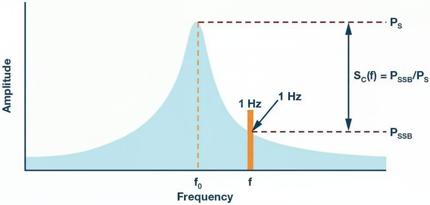
Phase noise is an alternative way to quantify timing variations of a signal, presented in the frequency domain. Using an oscillator signal to explain phase noise: without phase noise, all of an oscillator's power would be concentrated at f = f0. Phase noise spreads part of that power into adjacent frequencies, creating sidebands. As shown in the figure below, at a certain offset from the center frequency the sideband power rolls off as 1/fm, where fm is the frequency offset from the center.
Phase noise is commonly specified as dBc/Hz at a given offset frequency, where dBc is the power at that frequency relative to the carrier power expressed in decibels. An oscillator's phase noise at a given offset is defined as the signal power in a 1 Hz bandwidth at that offset relative to the total carrier power.
Overview of Measurement Methods
There are six commonly used measurement techniques in industry:
- Direct spectrum measurement
- Phase detector measurement
- Reference source / PLL measurement
- Frequency discriminator measurement
- Heterodyne (digital) phase detector measurement
- Two-channel cross-correlation measurement
This article focuses on the first method: the direct spectrum measurement technique.
Direct Spectrum Method for Phase Noise
The direct spectrum method is the simplest and most classical approach. Feed the device under test (DUT) signal into a spectrum analyzer or signal analyzer, tune the analyzer to the DUT frequency, and directly measure the oscillator power spectral density S(f). Because this method measures the spectral density in the presence of the carrier, the analyzer's dynamic range strongly affects the measurable range.
Although this method is not ideal for measuring phase noise very close to the carrier, it is convenient and fast for characterizing sources with relatively high noise. The measurement is valid when the following conditions are met:
- The analyzer's own SSB phase noise at relevant offsets must be lower than the DUT noise.
- Because the analyzer measures total noise power, it does not distinguish AM noise from phase noise. The DUT's AM noise must be much lower than its phase noise (typically by 10 dB) for the result to represent phase noise.
Typical Measurement Procedure Using a Spectrum Analyzer
The following steps describe a general procedure for measuring phase noise with an analyzer that has spectrum analysis capability.
- After connecting the DUT to the analyzer, set the analyzer center frequency to the DUT frequency and choose an appropriate analysis span (frequency span). Use the analyzer's marker-to-center function and reduce the span until the carrier is centered on the screen and the span is appropriate. The span should equal or slightly exceed twice the offset frequency of interest.
- Set an appropriate reference level on the analyzer. The reference level should be slightly higher than or equal to the DUT carrier output level. Use the marker-to-reference-level function if available. If the DUT carrier power is low, use the smallest attenuation setting that avoids compression.
- Set resolution bandwidth (RBW) and video bandwidth (VBW). If the analyzer links these parameters automatically, no manual action is needed. Otherwise set them manually. Avoid setting RBW or VBW too large, which degrades accuracy, or too small, which slows measurement. A common approach is to start with a larger RBW and reduce it until the measured phase noise no longer decreases.
- Enable trace averaging. Enable the marker and perform a peak search, then enable a delta marker and set the delta to the desired offset frequency. Activate the noise marker function. The value shown by the noise marker is the phase noise at that offset, in dBc/Hz.
Measurement Considerations
- Choose a high-performance analyzer: Use an analyzer with low system noise floor. The DUT noise should be worse than the analyzer noise by at least 3 dB for a valid measurement. The direct spectrum method is not suitable for very low-noise high-performance oscillators or frequency sources.
- Measured result is composite noise: The measurement shows the sum of AM and FM noise. To obtain an accurate phase-noise measurement, the DUT's AM noise should be much lower than its FM noise (typically by more than 10 dB), so the result approximates phase noise.
- Consider analyzer dynamic range: The analyzer dynamic range determines the measurable span. Its lower limit depends on analyzer sensitivity and phase noise; the upper limit is set by the 1 dB compression point.
- Minimize environmental influences: Frequency drift can introduce large errors or prevent measurement. Allow the DUT and the analyzer to warm up until stable; a typical analyzer warm-up is more than 10 minutes. Ensure solid instrument connections, avoid vibration, and if possible place the setup on a vibration-damping pad. Where feasible, conduct measurements in a shielded room to reduce environmental interference.
- Apply corrections when needed: Many older analyzers using analog IF stages employ logarithmic IF amplifiers and peak detectors; add a 2.5 dB correction to such measurements.


