Classification of Measuring Tools
Measuring tools are devices with fixed shapes used to reproduce or provide one or more known quantities. By purpose, gauges can be divided into the following categories:
1. Single-value gauges
Gauges that represent a single, fixed value. They can be used to calibrate and adjust other measuring tools or to directly compare a standard value with the measured item, for example gauge blocks and angle gauges.
2. Multi-value gauges
Gauges that represent a set of similar values. They are also used to calibrate and adjust other measuring tools or to serve as standards for direct comparison, such as line scales.
3. Specialized gauges
Gauges designed to inspect a specific parameter. Common examples include limit gauges for smooth cylindrical holes or shafts, thread gauges for checking internal or external thread acceptability, inspection templates for complex surface profiles, and functional gauges that use analog assembly fit to verify assembly accuracy.
4. General-purpose gauges
In China, instruments with relatively simple structures are commonly referred to as general-purpose gauges. Examples include calipers, outside micrometers, and dial indicators.
Technical Performance Indicators of Measuring Tools
1. Nominal value of a gauge
The value marked on the gauge to indicate its characteristic or to guide its use, for example dimensions marked on gauge blocks, scales, or angle gauges.
2. Graduation value
The difference in measured quantity represented by two adjacent graduation marks on a gauge scale (the smallest unit). For example, if adjacent marks on a micrometer thimble represent 0.01 mm, then the graduation value is 0.01 mm. The graduation value is the smallest unit directly readable from the gauge and reflects the reading resolution and, indirectly, the measurement accuracy.
3. Measuring range
The range from the lower limit to the upper limit of values that the gauge can measure within its allowable uncertainty. For example, outside micrometers commonly have ranges of 0–25 mm, 25–50 mm, etc., and a mechanical comparator may have a measuring range of 0–180 mm.
4. Measuring force
The contact pressure between the probe of the measuring tool and the measured surface during contact measurement. Excessive measuring force can cause elastic deformation; too little force can affect contact stability.
5. Indication error
The difference between the instrument indication and the true value of the measured quantity. Indication error reflects the combined effect of various instrument errors; it varies across different operating points within the instrument's indication range. Indication error is typically verified using gauge blocks or other calibration standards with appropriate accuracy.
Selecting Measuring Tools
Before each measurement, select measuring tools based on the specific features of the part to be measured. For example, for length, width, height, depth, outside diameter, or step differences, use calipers, height gauges, micrometers, or depth gauges as appropriate; for shaft diameters use micrometers or calipers; for holes and slots use plug gauges, ring gauges, or feeler gauges; use squares for right-angle checks; use radius gauges for R values; when fit tolerances are tight or high precision or form/position tolerances need calculation, consider using 2D or 3D measuring machines; use hardness testers for measuring steel hardness.
1. Caliper applications
Calipers can measure internal and external diameters, lengths, widths, thicknesses, steps, heights, and depths. They are the most commonly used and convenient gauge on the shop floor.
Digital calipers: resolution 0.01 mm, used for dimensions with tight fit tolerances or higher accuracy requirements.
Dial calipers: resolution 0.02 mm, used for routine dimensional measurements.
Vernier calipers: resolution 0.02 mm, used for rough machining measurements.
Before using a caliper, remove dust and dirt by using a clean white sheet of paper: clamp the paper between the caliper jaws and slide it out naturally, repeating 2–3 times.
Notes:
- When measuring with a caliper, keep the measuring faces as parallel or perpendicular to the measured surface as possible.
- When using the depth rod, avoid R corners but keep close to them; maintain the depth rod perpendicular to the measured surface.
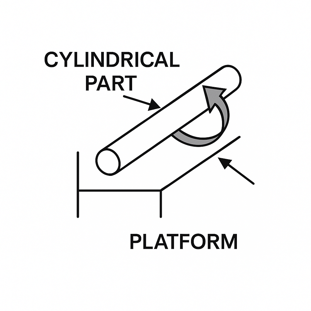
- When measuring round parts, rotate and take sectional measurements to record the maximum value.
Because calipers are used frequently, maintenance is important. After daily use, wipe clean and store in a case. Verify caliper accuracy with gauge blocks before use.
2. Micrometer applications
Before using a micrometer, remove dust and dirt by clamping a clean white sheet between the measuring faces and spindle, then slide out naturally 2–3 times. Turn the ratchet until the measuring faces are nearly in contact, then use the fine adjustment. After faces contact, zero the micrometer and measure.
When measuring metal parts, turn the ratchet until contact, then use the fine adjustment; when three audible clicks are heard, stop and read the value from the scale or digital display.
When measuring plastic products, allow the spindle to lightly contact the part surface.
When measuring shaft diameters, measure in at least two directions and take sectional measurements to record the maximum value. Keep the contacting faces clean to reduce measurement error.
3. Height gauge applications
Height gauges are used to measure heights, depths, flatness, perpendicularity, concentricity, coaxiality, surface runout, and gear runout. Before measurement, check that the probe and all connections are secure and not loose.
4. Feeler gauge applications
Feeler gauges are suitable for measuring flatness, warp, and straightness.
Flatness measurement: place the part on a surface plate and use feeler gauges to measure gaps between the part and the plate. During measurement, press the feeler gauge so that it is snug between the part and the plate.
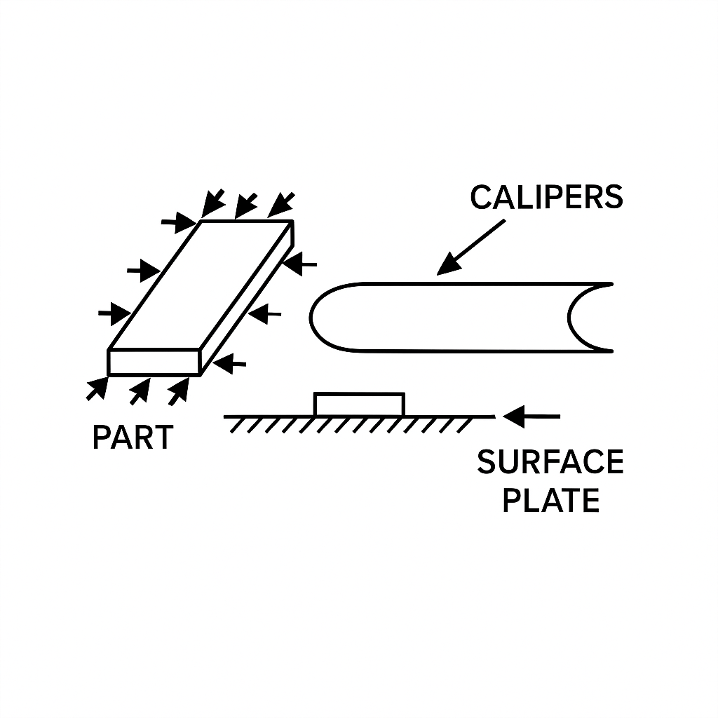
Straightness measurement: place the part on the surface plate, rotate it 360 degrees, and measure gaps between the part and the plate with feeler gauges.
Warp measurement: place the part on the surface plate and use the appropriate feeler gauge to measure gaps between the part sides or middle and the plate.
Perpendicularity measurement: place one edge of the part with a right angle on the surface plate, press a square against the other edge, and use feeler gauges to measure the maximum gap between the part and the square.
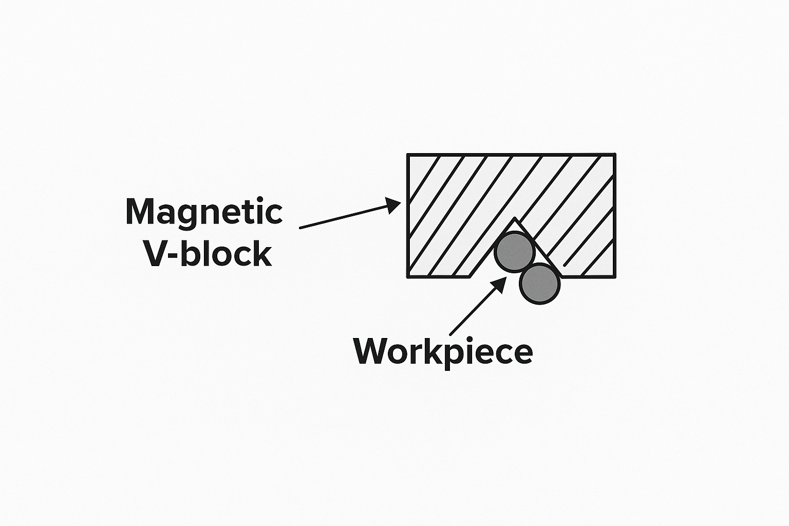
5. Plug gauges and pins
Used for measuring interior diameters, slot widths, and clearances.
If a part aperture is large and no single pin gauge fits, two plug gauges can be stacked and measured around 360 degrees. Fixing plug gauges on a magnetic V-block prevents loosening and facilitates measurement.
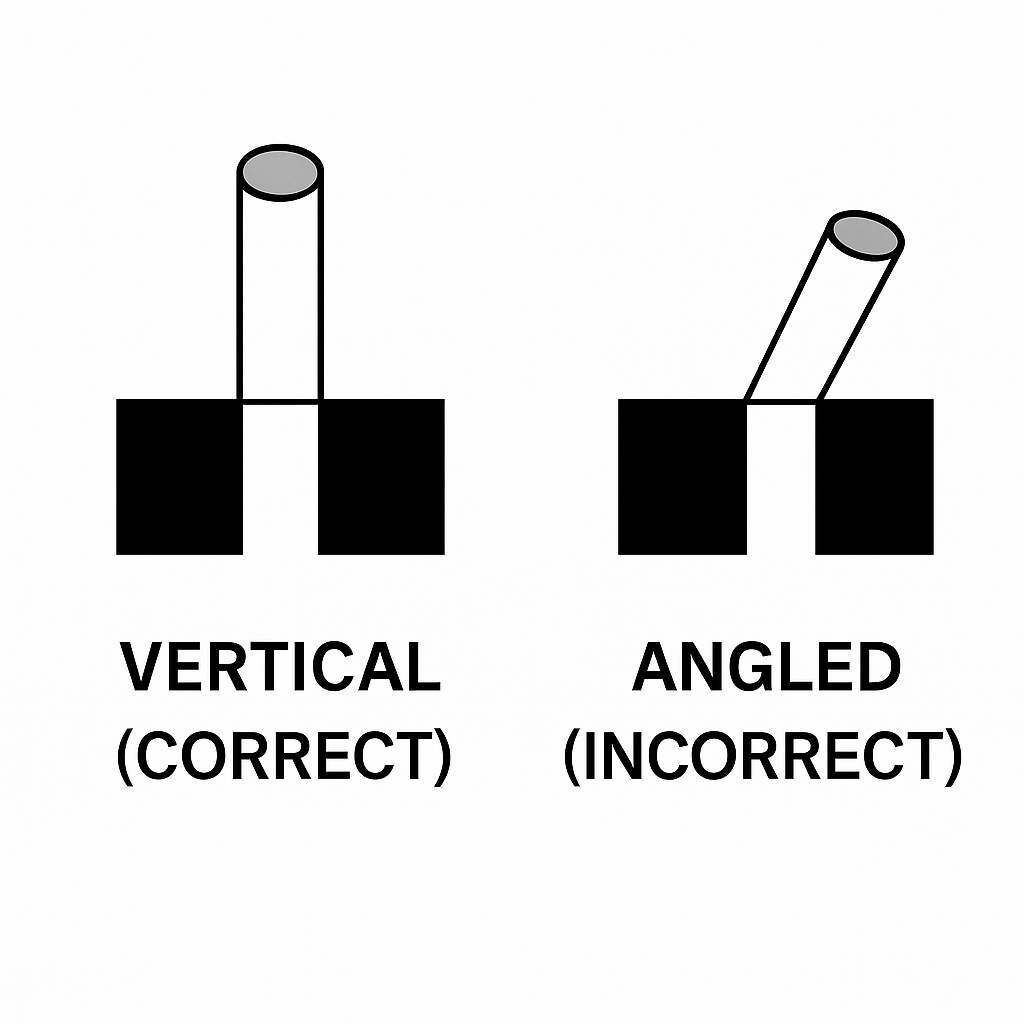
Through-hole measurement: when a plug gauge passes through the hole, the hole is acceptable.
Note: Insert plug gauges perpendicular to the hole; do not insert at an angle.
6. Optical comparator and 2D measuring systems
2D measuring systems are high-performance, high-precision non-contact instruments. The sensing element does not contact the part, so there is no measuring force. They project the captured image through a data line to a computer data acquisition card and display the image on-screen. They can measure geometric elements (points, lines, circles, arcs, ellipses, rectangles), distances, angles, intersections, and form/position tolerances (roundness, straightness, parallelism, perpendicularity, inclination, positional tolerance, concentricity, symmetry), and can output 2D profiles to CAD. They can observe part outlines and measure surface shapes of opaque parts.
Common geometric element measurement: the inner circle in the figure has sharp edges and must be measured by projection.
Electrode surface inspection: the 2D system lens provides magnification for roughness inspection after electrode machining (e.g., 100x magnification).
Gate inspection: in mold processing, some gates are hidden in grooves and are difficult to measure with conventional instruments. Apply rubber clay to the runner so the gate shape is imprinted in the clay, then measure the clay imprint with a 2D system to determine gate dimensions.
Note: Because 2D measurement does not exert mechanical force, it is preferable for measuring thin or soft products.
7. Coordinate measuring machines (CMM)
CMMs offer high accuracy (down to the micrometer level), versatility (can replace many length gauges), and the ability to measure geometric elements beyond 2D systems, including cylinders and cones. Form/position tolerances measurable by CMMs include cylindrical form, flatness, line profile, surface profile, and coaxiality. Any surface reachable by the probe can be measured for geometric dimensions and relative positions; data processing is performed with computer support. Due to their accuracy, flexibility, and digital capabilities, CMMs are important tools in modern mold manufacturing and quality assurance.
When modifying molds without 3D files, one can measure coordinate values of various elements and contours of irregular surfaces, export them to drawing software, and reconstruct a 3D model for accurate machining and modification. Once coordinates are set, arbitrary points can be measured for coordinate values.
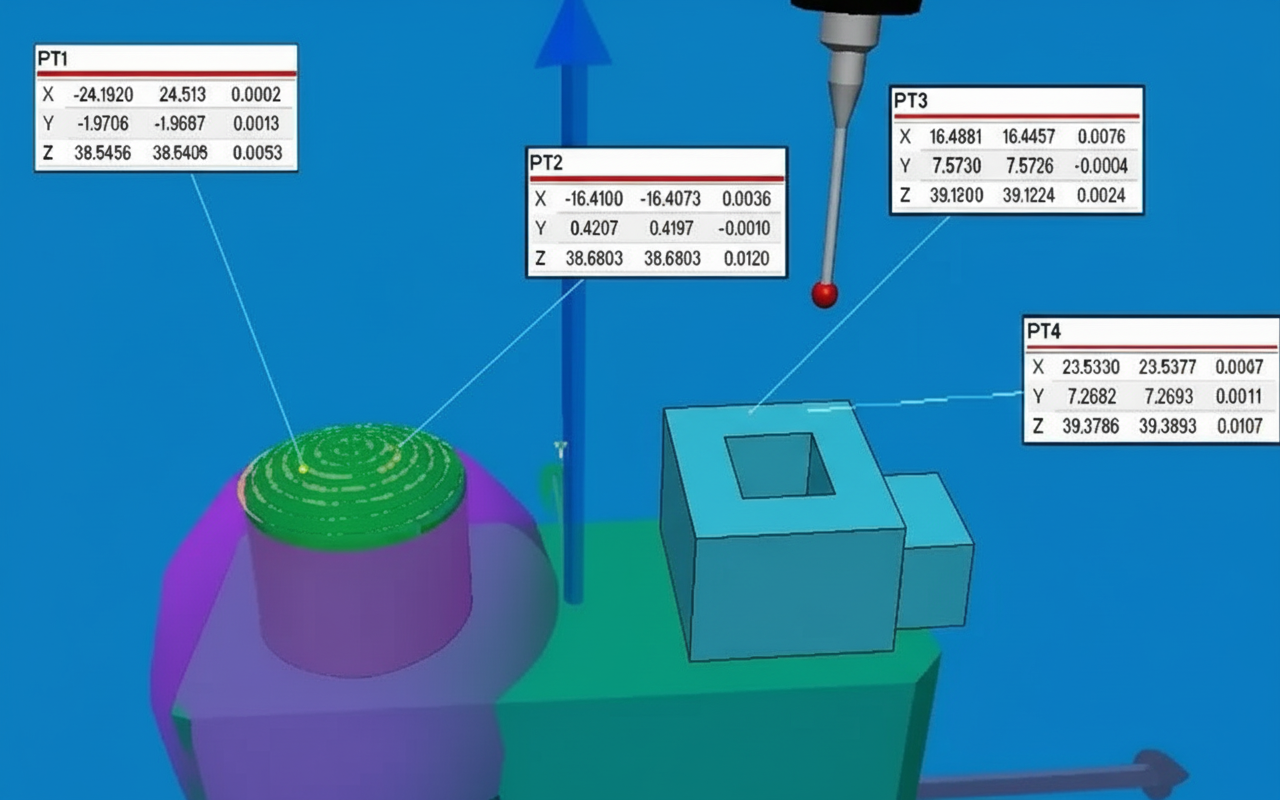
3D CAD comparison measurement: to verify conformity with design or to identify fit issues during assembly, import the 3D model and compare it with the part. This reveals machining errors as point-to-point deviations, facilitating fast and effective correction.
8. Hardness tester applications
Common hardness testers include Rockwell (bench) and Leeb (portable). Common hardness units are HRC (Rockwell C), HB (Brinell), and HV (Vickers).
Rockwell hardness HR (bench tester):
The Rockwell method uses either a 120° diamond cone indenter or hardened steel balls of specified diameters under defined loads, and hardness is determined from the indentation depth. Different scales are used based on material hardness, such as HRA, HRB, and HRC.
HRA uses a 60 kg load and a diamond cone indenter for very hard materials, e.g., cemented carbides.
HRB uses a 100 kg load and a hardened steel ball (1.58 mm diameter) for softer materials, e.g., annealed steel, cast iron, copper alloys.
HRC uses a 150 kg load and a diamond cone indenter for very hard materials, e.g., quenched and tempered steels and some stainless steels.
Vickers hardness HV (mainly for surface hardness):
Suitable for microscopic analysis. Using loads up to 120 kg and a 136° diamond square pyramid indenter, measure the diagonals of the indentation. Suitable for large workpieces and deeper surface-layer hardness measurements.
Leeb hardness HL (portable tester):
Leeb hardness is a dynamic test method. The impact body of the hardness sensor strikes the surface and the ratio of rebound velocity to impact velocity at 1 mm from the surface, multiplied by 1000, defines the Leeb hardness value.
Advantage: Portable Leeb testers allow handheld hardness detection in various orientations directly on production floors, which is difficult for bench testers to perform.


