Help
  • FAQ
    browse most common questions
  • Live Chat
    talk with our online service
  • Email
    contact your dedicated sales:
0

Two Methods to Test a LIN Bus

Author : AIVON | PCB Manufacturing & Supply Chain Specialists February 20, 2026


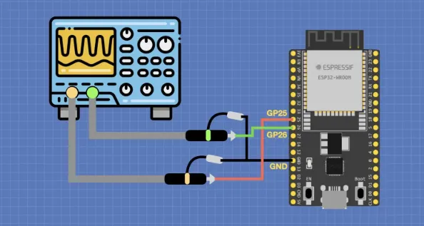
1. Oscilloscope measurement

[1] No data waveform. When no data communication occurs, the LIN signal DC average voltage is about 12 V. This voltage is the idle voltage of the LIN signal.

LIN idle waveform

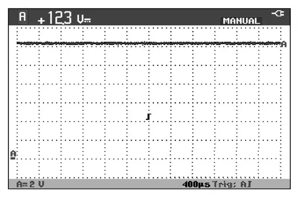
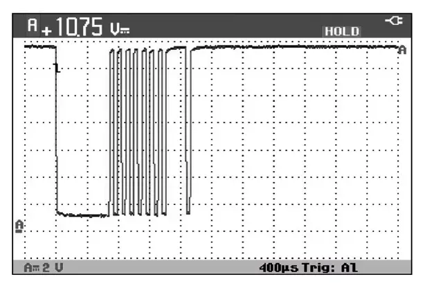
[2] Data waveform present. When the LIN bus is transmitting data, the LIN signal DC average voltage is about 10 V and varies dynamically. During communication the LIN signal valley voltage is about 1 V and the peak voltage is about 12 V.

LIN data waveform


2. Multimeter detection method

When measuring the LIN bus, note that if the bus is not transmitting data the voltage reads about 12 V. LIN is a master-slave protocol bus; all actions of slave control units are governed by the master module. During measurement you can operate related components, such as the driver-side door control panel, so the master control unit will issue commands over the LIN bus.

AIVON | PCB Manufacturing & Supply Chain Specialists AIVON | PCB Manufacturing & Supply Chain Specialists

The AIVON Engineering and Operations Team consists of experienced engineers and specialists in PCB manufacturing and supply chain management. They review content related to PCB ordering processes, cost control, lead time planning, and production workflows. Based on real project experience, the team provides practical insights to help customers optimize manufacturing decisions and navigate the full PCB production lifecycle efficiently.

Related Tags


2026 AIVON.COM All Rights Reserved
Intellectual Property Rights | Terms of Service | Privacy Policy | Refund Policy