Overview
Ultrasonic infrared thermography combines selective heating with infrared imaging to detect cracks and defects in complex workpieces, making it a valuable non-destructive testing method.
A research team from Nanjing Novell Photoelectric Systems Co., Ltd and Shanghai Composite Materials Technology Co., Ltd published an article in the journal Infrared Technology titled "Research Status and Progress of Ultrasonic Infrared Thermography in China." The lead and corresponding author is Jiang Haijun, who focuses on infrared nondestructive testing and image processing.
This article summarizes the principles and system components of ultrasonic infrared thermography, reviews the research progress in China, and details application areas including simulation studies, composite material damage, fatigue cracks, metal component cracks, and concrete part cracks. The article concludes with an outlook on future development directions for the technique.
Ultrasonic Excitation System
An ultrasonic infrared thermography system typically consists of an ultrasonic excitation source, an infrared image acquisition system, and an infrared image processing system. The ultrasonic excitation source comprises an ultrasonic power supply, ultrasonic transducer, and ultrasonic probe. The infrared acquisition system generally uses an infrared camera to capture thermal images. The principle of the system is shown in Figure 1. Synchronization is required between infrared image acquisition and ultrasonic excitation. When the ultrasonic probe injects energy into the specimen surface, the infrared camera begins to collect images covering both the heating and cooling stages of the defect.
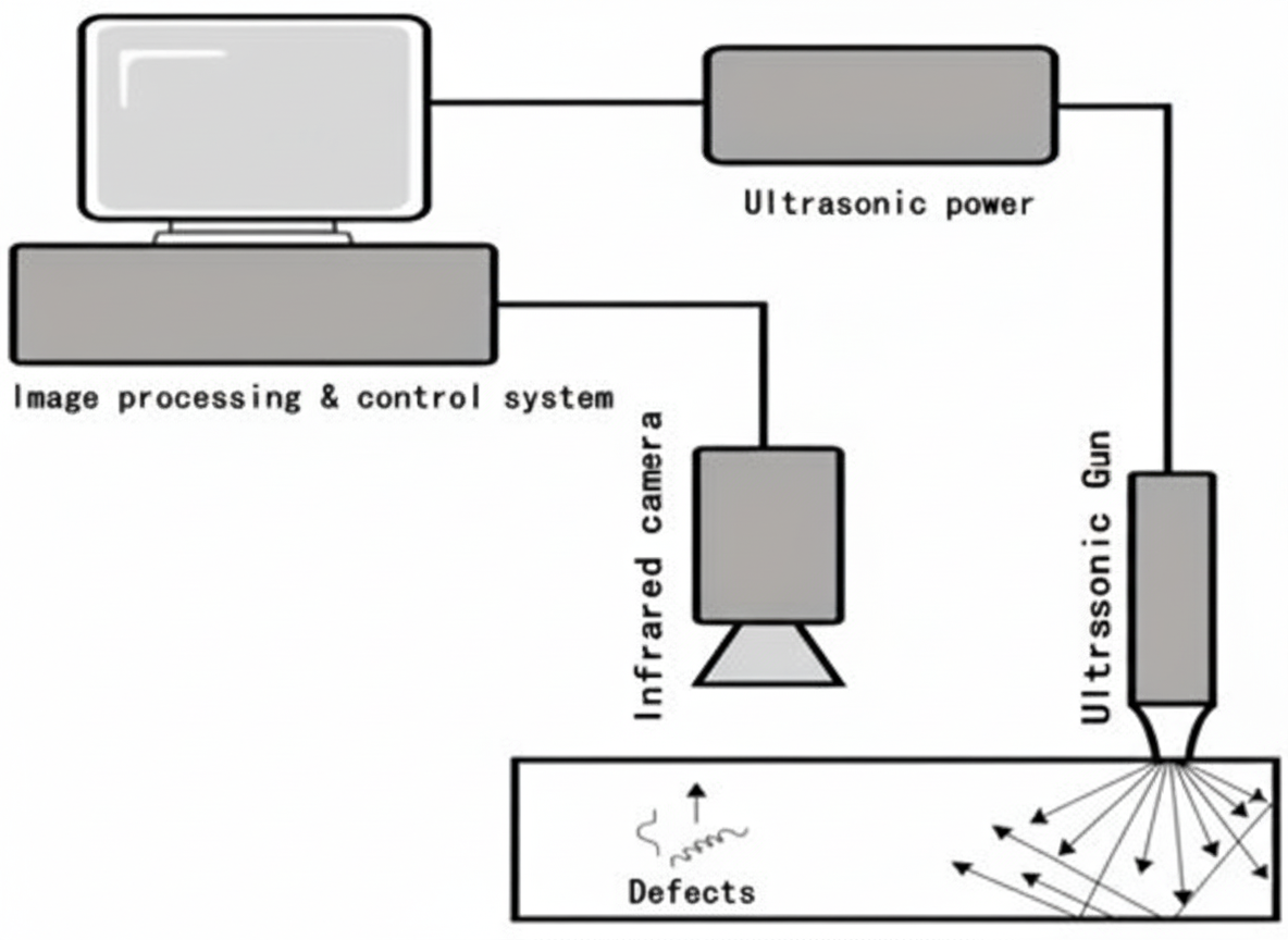
Figure 1 Principle of ultrasonic infrared thermography
Ultrasonic infrared thermography research began at the University of Virginia in 1979. In 2000, Lawrence Dale Favro and colleagues at Wayne State University first used an ultrasonic welding generator as an excitation source to detect metal fatigue cracks. In 2003, Zhang Shuyi et al. at Nanjing University applied ultrasonic infrared thermography to detect fatigue cracks in aluminum alloy plates.
In recent years, many research teams in China have investigated ultrasonic infrared thermography. Key research areas include theoretical simulation, metal crack detection, fatigue crack detection, turbine blade crack detection, and composite impact damage. Specific focuses by institutions include:
- Beihang University: delamination/impact defects in composites.
- Harbin Institute of Technology: metal surface cracks and phase-locked ultrasonic infrared thermography.
- Armored Corps Academy: simulation and the influence of excitation parameters (preload, fixture, excitation method, excitation location) on detection results; applied research on armored equipment defect detection.
- Hunan University: flat-bottom hole defects and impact damage in composites.
- Rocket Force Engineering University: alloy steel cracks, complex-surface cracks, and composite impact damage.
- Fuzhou University: effects of ultrasonic excitation parameters (direction, frequency, amplitude) on weld crack detection in metals.
Southwest Jiaotong University has studied ultrasonic excitation for detecting cracks in concrete slabs. The Nanjing Hydraulic Research Institute has examined how excitation frequency, power, preload, and acoustic absorption affect concrete crack detection. China Southern Aero-Engine Co., Ltd and Nanjing Novell Photoelectric Systems Co., Ltd have researched blade crack detection before and after coating in aero-engines. Wuhan University of Technology has investigated detection of bolt joint cracks and delamination in composites.
The core hardware of an ultrasonic infrared thermography system is the preload unit and fixture unit. The preload unit is typically realized by mechanical springs or pneumatic systems. The fixture unit must be optimized for the specimen structure and can use medical tape or rigid coupling to couple ultrasound into the specimen. These differences in coupling and fixturing lead to variety in system designs.
Main Application Areas
Simulation Studies
Simulations of composite-material cracks with different curvatures show that greater curvature increases the slope during the heating phase, making defect signals easier to excite. Numerical simulation studies of multi-mode ultrasonic excitation indicate that multi-mode excitation effectively suppresses standing waves while generating richer subharmonic and higher harmonic content, improving detection capability. Three-dimensional crack simulations using ANSYS and ABAQUS combined with modal and harmonic response analyses can obtain specimen natural frequencies, providing theoretical guidance for selecting ultrasonic excitation frequencies. Numerical analyses of a 10 μm titanium alloy crack using ANSYS showed results consistent with experiments. ANSYS has also been used to simulate concrete slab cracks to support crack detection studies in concrete.
Composite Material Damage
Composite materials offer high specific strength and stiffness, corrosion and aging resistance, and high-temperature performance, and are widely used in aerospace, new energy, construction, automotive, and sporting goods. Under low-velocity impact, composites are vulnerable to matrix cracking, delamination, and fracture. J. Rantala, G. Busse, and others were among the first to use ultrasonic infrared thermography to detect internal defects in composites. Numerical models have been developed to simulate composite impact damage with embedded cracks. Experimental and numerical studies show the technique's applicability to detecting impact damage in composites and the influence of bolt preload on heating behavior around bolt-hole damage.
Studies comparing ultrasonic infrared thermography with C-scan imaging show that thermography provides faster, higher-precision, and more intuitive results. For example, tests at various low-velocity impact energies (10–50 J) show that larger impact energies produce larger damage areas; woven composites exhibit crack extension behavior under impact.
Fatigue Cracks
Studies have validated ultrasonic infrared thermography for detecting metal fatigue cracks. Investigations on 7075 aerospace aluminum alloys examined excitation parameters and the relationship with heating behavior, finding that an excitation source located 15 mm from the crack provides optimal detection. Both side and front excitation can detect fatigue cracks in 7075 aluminum, with side excitation performing better. Detection of substrate fatigue cracks under coating layers (300–400 μm thickness) has been demonstrated. Simulations of crack opening widths (5–30 μm) show that larger openings reduce contact and frictional heating, so wider openings can yield lower peak temperatures; experiments confirmed these findings.
Metal Component Cracks
Detecting cracks in metal components, especially complex-shaped parts, is challenging for optical excitation thermography. Studies on large aluminum aircraft structures showed good detection of closed cracks. Research indicates that maximum heating occurs when excitation is applied at optimal positions. Comparative testing on wheel hubs found ultrasonic infrared thermography better at revealing internal cracks and crack propagation directions than magnetic particle inspection. Detection of an L-shaped central crack and corner cracks in a 35 kg locomotive coupler tongue has been reported.
Research on armored vehicle hull cracks demonstrated fast detection capability, with crack detection achievable within 3.5 s. In one test, an 8 kg forged steel block with an end-face crack was examined. Figure 5 shows the specimen, and Figure 6 shows detection results before and after excitation; the results reveal a previously unseen branched crack and an embedded crack, demonstrating the technique's sensitivity to cracks not visible to the naked eye.
Aero-Engine Blade Cracks
Turbine blades are subjected to alternating tensile stress, thermal corrosion, torsion, and high-speed impact, making them prone to cracking. Small cracks can grow under service loads and threaten flight safety. Traditional nondestructive methods have limitations for complex blade geometries. Ultrasonic infrared thermography is relatively insensitive to specimen shape, and has been widely investigated for blade inspection.
Studies include inspection of 60 turbine blades to assess reliability, ANSYS simulations of crack heating in alloy blades, and experiments using laser-cut pre-cracks. Research has also examined the effect of preload on detection. Ultrasonic infrared thermography has detected cracks as narrow as 0.5 μm in working blades, which were not detected by dye penetrant inspection, indicating an advantage for detecting very small cracks. Tests on coated and uncoated hollow blades showed that fluorescent penetrant inspection can miss cracks in coated hollow blades, whereas ultrasonic infrared thermography is less affected by coating and blade structure and can detect cracks in coated hollow blades.
Concrete Part Cracks
Cracks are common defects in concrete structures and severely weaken load-bearing capacity, accelerate aging, and compromise safety and durability. Detection and remediation of cracks are important engineering tasks. Infrared thermography based methods have been used to derive quantitative formulas for defect depth in concrete. Ultrasonic infrared thermography has been shown to detect microcracks and hidden cracks not visible to the naked eye in concrete specimens.
Vibration thermography and acoustic excitation devices (including sonic and ultrasonic sources with low- and high-power options) have been developed to study the effects of excitation frequency, power, and preload on acoustic absorption. Tests on pre-cracked concrete specimens with standardized microcracks indicate that ultrasonic-excited thermography can detect concrete cracks with widths of 0.01–0.09 mm. ANSYS simulations of V-shaped cracks in concrete slabs have been used to analyze heating mechanisms and the influence of excitation position, duration, and frequency. Figure 2 shows thermography detection of concrete cracks with the cracked regions circled.
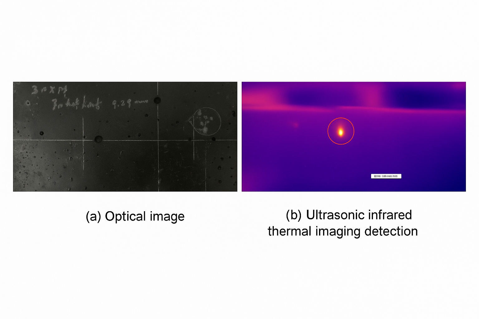
Figure 2 Concrete crack detection
Development Trends
Ultrasonic infrared thermography can detect cracks as small as 0.5 μm in metals, 1.0 μm in composites, and on the order of 10 μm in concrete. The method selectively heats crack regions while leaving intact regions relatively unaffected, making it suitable for complex structures and materials such as metals, concrete, aero-engine blades, and composite materials.
Compared with optical excitation methods, ultrasonic excitation requires specimen fixturing and application of preload to the excitation head. Because fixtures must be tailored to specimen types—for example, fatigue crack fixtures for metals and specialized fixtures for aero-engine blades—ultrasonic systems are more complex and varied. However, for repeated inspections of the same specimen type, standardized fixtures and testing procedures can be developed, indicating broad future prospects. Future research priorities include the following:
- Optimization of excitation hardware. Excitation devices require both fixture and preload units. Fixtures must be custom-designed for each specimen, while preload units can be mechanical or pneumatic. Mechanical preload units are compact and simple but require manual operation to apply or release preload. Pneumatic preload units are larger and more complex but can be automated for preload application and release. Integrating ultrasonic excitation, automated assembly, infrared image acquisition, and image processing into a unified industrial system would facilitate crack inspection applications.
- Standardization of testing. Ultrasonic excitation differs significantly from optical excitation and depends on operator experience. Excitation location, duration, and coupling efficiency all influence detection results. Developing unified testing protocols and technical standards for ultrasonic infrared thermography will accelerate engineering adoption.
- Automated defect recognition. Ultrasonic infrared thermography typically acquires hundreds of frames per inspection sequence, and identifying defects manually from such sequences is time-consuming and operator-dependent, which can lead to false positives and missed defects. With the rise of artificial intelligence and deep learning, models that learn image feature representations from large datasets can enable automated and more reliable defect detection.
Conclusion and Outlook
After decades of development, ultrasonic infrared thermography has made notable advances in heating mechanisms, simulation, defect detectability, and application across materials. However, industrial adoption lags behind optical excitation thermography. Flash thermography has already been standardized and is used in industrial inspections such as composite bonding quality in aircraft, thermal protection system delamination, and thermal barrier coating defects, with mature industrial equipment available. Ultrasonic infrared thermography remains primarily at the laboratory stage, but as technology advances and industrial demand—particularly in aerospace—for crack detection grows, ultrasonic infrared thermography is expected to move gradually into industrial and aerospace inspection applications.


