Abstract
CAN Bus-Off results from the accumulation of error frames. An error frame is produced when a receiving node detects a perceived error and intentionally interrupts communication so that the transmitting node can detect the condition and retransmit. This creates a "I think you are wrong" cognitive trap that makes CAN diagnostics seem mystical. This article describes a method that uses CAN waveform amplitude and pulse-width information from an oscilloscope to precisely locate the source of error frames.
Overview of a Typical CAN Node
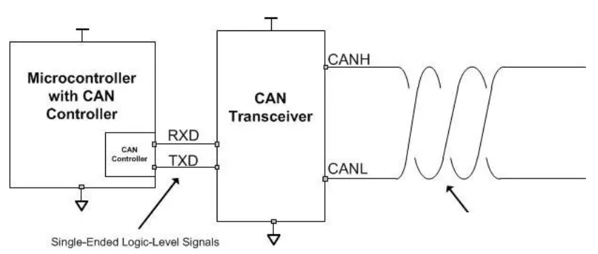
A typical CAN node includes an MCU with a built-in CAN controller that packages MCU data into CAN frame format and handles CRC and error-frame logic. The controller sends the logical TX/RX signals to a CAN transceiver, which converts the logic signals to bus differential waveforms.
1. CAN Physical Layer
What does the CAN transceiver do?
A typical two-node CAN physical layer equivalent circuit shows two 120 ohm termination resistors in parallel, presenting a 60 ohm bus resistance. The transceiver performs level conversion. When the bus is idle, the transceiver biases CAN-H and CAN-L to 2.5 V through 15 kΩ resistors; this idle state is recessive. When node A drives the bus (TX=0), it turns on upper and lower MOSFETs and drives current through the network: A's 5 V through protection diode, 24 ohm, parallel termination resistors, 24 ohm, diode back to ground. This state is dominant. The bus voltages at node B become about 3.5 V on CAN-H and 1.5 V on CAN-L, yielding a differential H-L ≈ 2 V, which exceeds the 0.7 V threshold so node B sees RX=0. The bus voltage is determined by the divider across the termination resistors; compute these values to reinforce understanding for later analysis.
Counterintuitive point 1: When no node drives the bus (all nodes recessive), CAN defines TX/RX logic as 1. When any node drives dominant, TX/RX logic is 0. This inverted polarity is similar to open-collector logic like I2C. This design likely improves ground-referenced noise immunity and ensures deterministic arbitration: any dominant bit forces the bus dominant. However, this inverted logic imposes constraints on power sequencing: do not allow the MCU to be unpowered while the CAN transceiver still has 5 V supply and TX is pulled low. If unavoidable, consider single-supply 3.3 V transceivers that do not require a separate 5 V supply.
Counterintuitive point 2: In theory, if CAN_L is shorted to ground or CAN_H is shorted to 12 V, the presence of the 60 ohm termination resistors keeps CAN-H and CAN-L near the same level when recessive and still allows a dominant differential to be produced when a node drives, so communication can continue albeit with higher packet loss. If you observe the bus center is not symmetric around 2.5 V, cross-wiring between different CAN lines is a possible cause.
Counterintuitive point 3: A CAN network can function with one to four 120 ohm terminators. With too few, nodes far from terminators have poorer immunity; with too many, the dominant differential may not exceed the threshold.
Counterintuitive point 4: Apart from the far ends, any moderately long CAN stub can include a 1 kΩ to 4.7 kΩ series resistor to bleed some current and improve immunity. For runs under roughly 1 Mbps, termination mostly provides current sharing rather than strict impedance matching; twisted pair requirements are not extremely strict.
2. CAN Link Layer
What does the CAN controller do?
When the MCU drives TX from 1 to 0, the transceiver pulls CAN-H high and CAN-L low. Receivers see H-L > 0.7 V and RX transitions from 1 to 0. The decoded RX logic is then interpreted by the CAN controller.
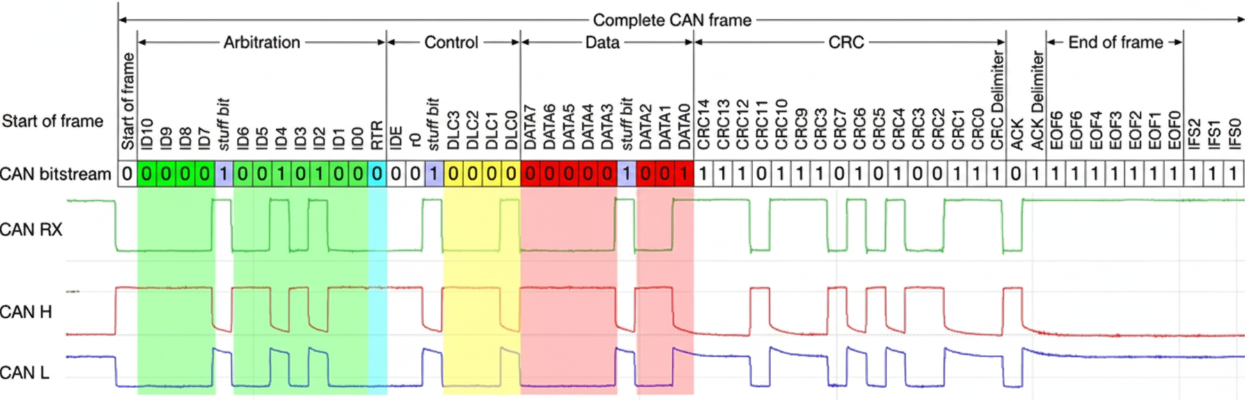
A CAN frame contains several key segments: arbitration, control, data, CRC, and ACK.
Arbitration field mostly contains the CAN ID. The term "arbitration" refers to the priority resolution: if nodes A and B transmit simultaneously with IDs 001 and 010, both drive dominant on the first bit. When A transmits a 0 and B transmits a 1 on a later bit, the bus remains dominant so B sees a mismatch and ceases transmission. The ID determines the frame's priority, not the node.
Counterintuitive point 1: CAN is a peer-to-peer broadcast network without master/slave roles. Message ID values define priority. System designers must plan message priorities and periods (communication matrix) to ensure correct operation. Identical nodes with only a single message may suffer when lower-priority IDs cannot gain bus access on a busy or noisy bus.
Counterintuitive point 2: When two nodes both drive the first dominant bit during arbitration, the bus differential will be higher than the usual 2 V. On an oscilloscope, this appears as a pronounced elevated plateau at the start of the arbitration field; once one node wins arbitration, the amplitude returns to the normal 2 V.
Counterintuitive point 3: Node clocks are synchronized by subdividing each bit into typically 16 to 20 quantum samples. Do not set this subdivision too high or too low. See vendor references for CAN synchronization details.
Control field contains control bits like IDE (identifier extension) and R0. If IDE is recessive, 18 more ID bits follow for extended 29-bit IDs. R0 is reserved; in CAN-FD it is repurposed as FDF. DLC indicates data length. In CAN-FD only the data field may switch to higher bit rates while other fields remain at the nominal rate.
Counterintuitive point 1: CAN-FD differs not only in data bit rate but also in frame control bits. FDF indicates FD format, BRS indicates whether to switch to the higher FD bit rate. An FD frame may still remain at the nominal rate if BRS is not set.
Counterintuitive point 2: ISO 11898-1 specifies legacy CAN controllers should ignore the R0 bit state, so legacy CAN devices cannot reliably filter FD frames. A legacy device that accidentally sends R0 as recessive could be interpreted as an FD frame on an FD network, resulting in format errors. Therefore, CAN-FD is not strictly backward compatible with legacy CAN devices.
Counterintuitive point 3: DLC in classic CAN encodes 0 to 8 bytes. In CAN-FD DLC values 9 to 15 map to 12, 16, 20, 24, 32, 48, 64 bytes respectively.
CRC covers the frame from start of frame to end of data; classic CAN uses CRC15 while CAN-FD uses wider CRC variants depending on data length.
ACK field is driven recessive by the transmitter and dominated (driven dominant) by receivers that consider the frame structure valid. The transmitter writes recessive and expects one or more receivers to pull dominant at ACK.
Counterintuitive point 1: Any node that believes the frame format is correct will drive ACK dominant, even if it does not need the message ID or data. This avoids MCU processing delays affecting link-layer timing.
Counterintuitive point 2: If the transmitter receives no ACK, it treats this as an error and will retry up to defined limits before entering error-passive or bus-off states.
3. Real CAN Waveforms
Here is a more complex in-vehicle waveform with more than four nodes:
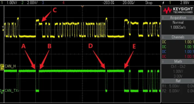
Yellow is CAN_H; a high level corresponds to dominant. Green is the test node TX; low corresponds to dominant. Arrows A to D indicate a complete CAN frame. Between A and B, the test node and another node participate in arbitration; simultaneous driving produces a higher amplitude plateau. At C the test node intends to send a recessive but sees dominant, meaning another node with higher priority is transmitting, so the test node stops transmitting and becomes a receiver. At D, after CRC checks pass, receivers assert ACK. The amplitude pattern lets you infer how many nodes are driving at each instant: higher plateaus indicate multiple nodes driving simultaneously.
4. Error Frames
An error frame is not sent by the original transmitter; it is produced when a receiving node decides the bus content is invalid and deliberately drives the bus to interrupt the transmitter. An error frame therefore requires a transmitter and at least one receiver that deems the transmission incorrect.
5. Bit Stuffing
Bit stuffing in CAN enforces the rule "after five consecutive identical bits insert one opposite bit." If a transmitter fails to insert the stuffing bit, or the stuffing bit is flipped by noise, the receiver detects a bit-stuffing error and transmits an Active Error Flag, which is six consecutive dominant bits, thereby intentionally corrupting the frame. The transmitter senses the error and stops sending the remainder of the frame. Note the clever reuse: six consecutive dominant bits violate the five-bit-stuff rule so they serve as the error indicator.
Example: data 0x00 bits 0000 0000. When the transmitter reaches five zeros it inserts a one and continues, so the transmitted sequence includes the stuffing bit. If stuffing is wrong, the receiver will flag stuffing error.
6. Readback Acknowledgement and Error Reaction
The transmitter reads back the bus while sending. If the readback does not match what the transmitter intended for that bit, the transmitter will generate an Active Error Flag (six dominant bits) to discard the remainder of the frame and signal error. When a receiver detects the six dominant bits, it also sends an Active Error Flag, so on the bus you may observe up to twelve consecutive dominant bits: six from the transmitter followed by six from the receiver.
In normal operation dominant runs on the bus should not exceed five consecutive bits (for classical CAN). Therefore, configuring an oscilloscope to trigger on pulse widths > 11 us is an effective way to locate error frames, even without protocol decode.
7. Additional Dimensions: Amplitude and Current
Waveform amplitude and bus currents add diagnostic dimensions.
In this trace the blue line is the differential H-L voltage and the purple line is the CAN-H pin current at node A. From the amplitude plateaus you can infer how many nodes were simultaneously driving at each point in the frame. The current trace reveals whether node A is sourcing or sinking current. For example, a plateau where current is zero indicates multiple nodes with termination resistors are driving such that no net current flows at node A. A negative current indicates current from other nodes flows into node A's termination. The ACK region typically shows larger negative current when multiple receivers assert ACK.
8. Practical Error Frame Case Studies
Case: two-node network. Transmitter uses TJA1042, receiver uses single-supply 3.3 V MAX3051. An error occurs in the frame header, often due to clock skew or incorrect sampling point.
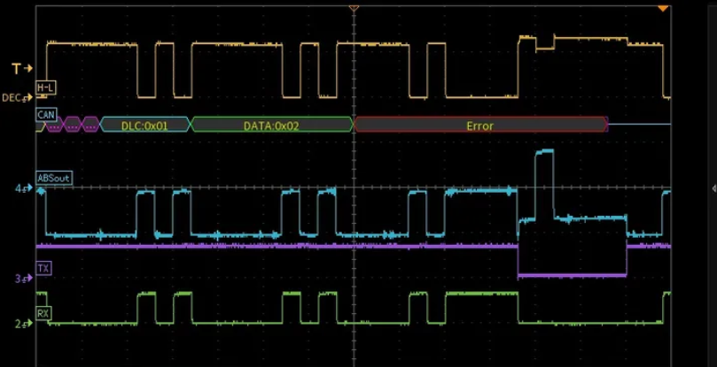
With a 500 kbps bit width of 2 us, the violet TX trace shows 12 us of dominant bits between two arrows, indicating the receiver issued an Active Error Flag. Looking earlier between arrows 1 and 2 the bus shows only 5 bits of dominant (10 us), but the receiver interpreted these 10 us as 6 bits—likely due to incorrect sampling point or excessive resynchronization width (SJW) in a poorly implemented MCU CAN controller, causing header errors.
Between arrows 2 and 3 the transmitter intended to send a recessive but the receiver was already driving an Active Error Flag, turning the bus dominant. The transmitter then detects its bit mismatch and also outputs an Active Error Flag, yielding the characteristic elevated plateau where both nodes drive simultaneously. The left and right shoulders of the plateau differ in amplitude because the receiver's MAX3051 drive strength is weaker than the transmitter's TJA1042, which helps identify different device types on the bus.
The blue current trace shows negative current during normal transmitter-driven periods (current flowing from transmitter into receiver termination). When the receiver drives the first bit of its Active Error Flag, current becomes positive at node A. During overlapping drive periods the stronger node dominates the current direction.
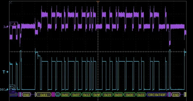
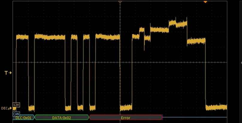
Another capture from the same two-node network shows a frame where DLC=0x01 so one data byte only. The Active Error Flag occurred in the CRC field. The transmitter continued attempting to send recessive bits during the receiver's Active Error Flag, indicating the transmitter did not immediately see a local error and only discarded the frame once the bus was driven dominant. The root cause was a sampling point set too early combined with an overly large SJW that accumulated clock error; resynchronization was inadequate and a bit was misread, producing a CRC error. Adjusting the sampling point and SJW reduced the error frequency and restored normal waveforms.
In another example the error occurs in CRC and analysis shows three nodes contributed to the 12 us Active Error Flag. By sliding 12 us windows backward from each amplitude step you can attribute which node drove the Active Error Flag segments. Node A likely miscalculated CRC due to earlier bit misreads. A node's local waveform quality may be poor due to stub ringing or lack of termination; node-local signal integrity issues can make that node sensitive to noise and more likely to flag errors.
9. CAN-FD Error Troubleshooting
Example: three-node CAN-FD network where node C transmits and nodes A and B receive. Differential H-L is yellow; node B TX is green. Two error frames 0x0677 and 0x0176 appear. FD data bit rate is 2 Mbps.
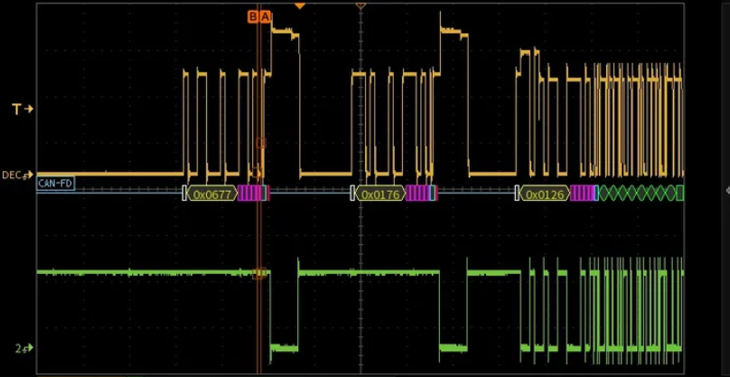
Zooming into 0x0176: the scale between markers A and B is about 0.8 us, which is a 2 Mbps FD bit of 0.5 us plus a CAN-FD timing compensation (TDC) of 300 ns. After that, six FD bits (0.5 us each) appear as continuous dominant, followed by 12 us of continuous dominant due to the Active Error Flag. A small voltage drop occurs roughly 12 us after marker B.
Interpretation: node C likely has excessive interference or a long branch; it failed to read back a bit in its local view and sent an Active Error Flag. Other devices detect a stuffing or framing violation earlier and also send their Active Error Flags. The high-rate FD stuffing rule applies to the FD bit rate, while Active Error Flags are transmitted at the nominal 500 kbps rate and always have a fixed duration of 12 us (six 2 us dominant bits).
Another CAN-FD case: sampling point misconfiguration caused node B to parse a CAN-FD frame as legacy CAN. Yellow CAN_H, green CAN_L, blue L-H reverse differential, violet node B RX, cyan node B TX.
Note the data section around 0x00 is at 2 Mbps. Node B misread the BRS bit (bit rate switch) due to sampling point settings and continued decoding at 500 kbps, causing it to see six consecutive dominant bits and declare a stuffing error. Node B then issued an Active Error Flag and interrupted the frame. Timing details: the BRS bit width is shorter than the surrounding control bits because it spans the sample point where the rate switch occurs. For example, with a receive sampling point at 80% of a 2 Mbps FD bit, the effective BRS bit width seen by receivers can be 1.7 us rather than 2.0 us. If a receiver sampling point is set beyond ~85%, it may miss BRS entirely and misinterpret the frame.
Summary
- With prior knowledge of which ID belongs to which node, sequentially disconnect non-terminating nodes and observe Active Error Flags on an oscilloscope to roughly localize the error source.
- If you can access a device's TX line, observing which device asserts an error makes it clear which node thinks another node erred.
- Measuring CAN pin output current helps identify which node drives the Active Error Flag and locate the fault.
- If direct access is limited, splitting error flag voltage plateaus into 12 us intervals can locate most error causes.


