Overview
At microwave frequencies, distributed-parameter analysis is required, and S-parameters are commonly used. S-parameters can be obtained from component manufacturers or measured directly by building a test fixture and using a network analyzer. A solid foundation in high-frequency electronic circuits is needed to fully understand S-parameters.
Why S-Parameters for RF and Microwave Design
For RF and microwave circuit design, lumped-circuit node analysis is no longer adequate. Distributed-parameter analysis or full-field methods are possible, but field analysis is often too complex. Microwave network analysis provides an equivalent-circuit approach that models microwave components as reactances or resistive elements and models real waveguides or transmission systems as transmission lines. This converts field problems into circuit problems and simplifies analysis.
With modern personal computers operating in the GHz range, many subsystems—from the CPU and display interfaces to memory buses and I/O interfaces—operate in high-frequency regimes. Thus, designers of RF communication circuits and even designers of computer and consumer electronics systems benefit from understanding S-parameters.
Signal and Power Considerations
Microwave systems deal primarily with two issues: signal characteristics (magnitude and phase vs frequency) and power transfer. Distributed-parameter circuits should be analyzed by field methods, but because those are often impractical, simplified network methods are used.
From Z/Y Parameters to S-Parameters
For networks, impedance (Z) and admittance (Y) parameters relate total port voltages and currents and are effective for lumped circuits. However, at microwave frequencies it is difficult to define or measure TEM-mode voltages and currents, and practical voltage and current measurements at these frequencies are challenging. Equivalent voltages, currents, impedances, and admittances thus become abstract.
S-parameters, based on incident and reflected waves, are a more practical representation for distributed circuits. The scattering matrix relates incident and reflected voltage waves at ports and is well suited to microwave analysis. S-parameters can be measured directly with a network analyzer and converted to other parameter sets when needed.
S-Parameters for a Two-Port Network
A two-port network has four S-parameters. Sij denotes the relationship between energy injected at port j and the energy observed at port i. S11 is the reflection coefficient at Port 1 (the ratio of reflected to incident voltage at Port 1). In practice, S-parameters are often represented as ratios of equivalent reflected and incident voltages. The physical meanings are:
- S11: reflection coefficient at Port 1 when Port 2 is matched;
- S22: reflection coefficient at Port 2 when Port 1 is matched;
- S12: reverse transmission from Port 2 to Port 1 when Port 1 is matched;
- S21: forward transmission from Port 1 to Port 2 when Port 2 is matched.
For reciprocal networks, S12 = S21.
For symmetric networks, S11 = S22. For lossless networks, |S11|^2 + |S12|^2 = 1.
Interpretation of S21 and S11
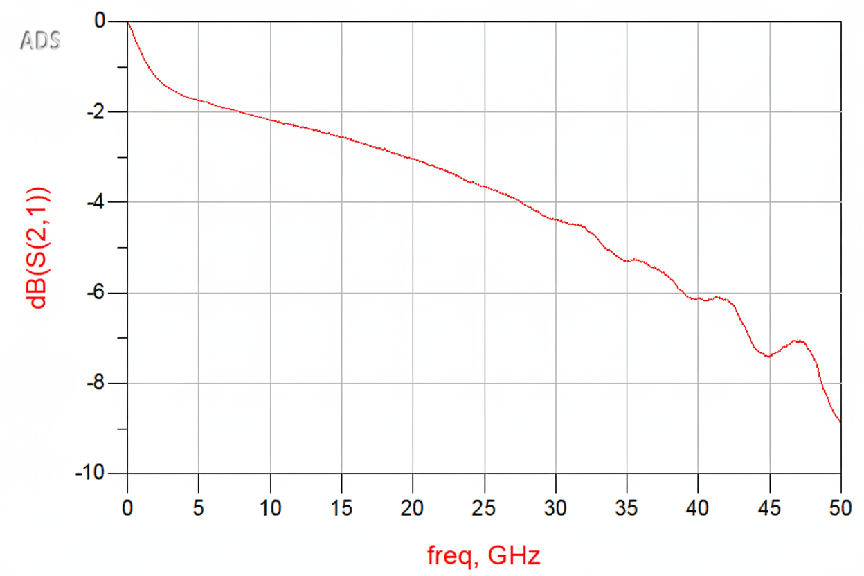
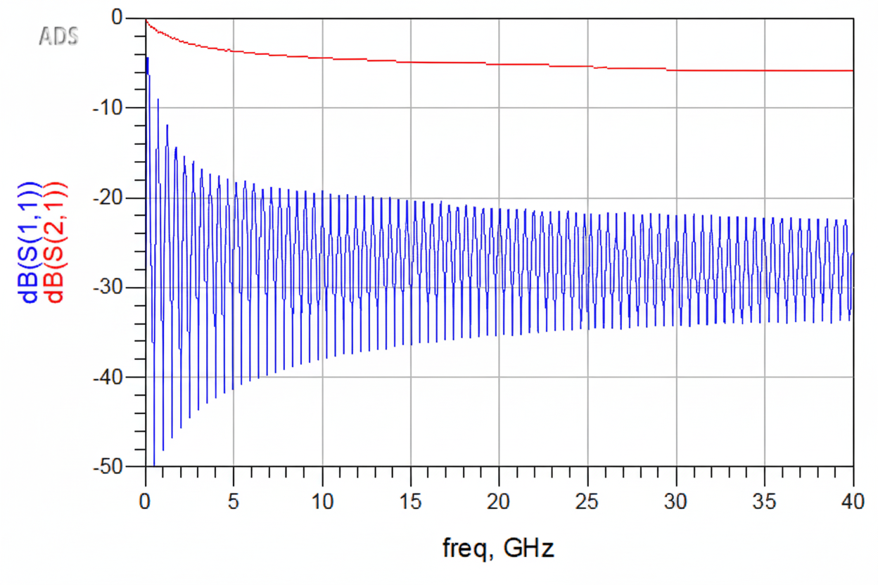
S21 represents insertion loss, i.e., how much energy is transmitted to the destination (Port 2). The ideal value is 1 (0 dB); larger S21 indicates higher transmission efficiency. A common guideline is S21 > 0.7 (approximately -3 dB).
S11 represents return loss, i.e., how much energy is reflected back to the source (Port 1). Smaller S11 is better. A common guideline is S11 << 0.1 (approximately -20 dB).
In an ideal lossless network, a small reflection at Port 1 can satisfy the S21 > 0.7 requirement. In real transmission lines, especially above GHz frequencies, conductor and dielectric losses are significant. Even with negligible reflection at the input, a long lossy transmission line will reduce S21 as energy is dissipated along the path.
Practical Use
S-parameters are widely used in high-speed signal testing. For example, a network analyzer can be used to measure the S-parameters of single-ended traces and differential pairs on a printed circuit board.


