The need to know water level is common in everyday situations, especially for opaque containers such as water tanks or fuel tanks. This article presents a simple water level measurement circuit and uses it to illustrate resistor circuit behavior.
Circuit components
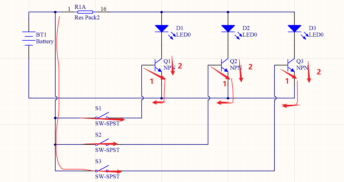
The circuit uses common electronic components: resistors, capacitors, transistors, LEDs, and a power supply. The circuit diagram is shown below; review it and try to analyze the signal paths.
Low water level indication
When the liquid in the container is very low, near the level of probe S3, only switch S3 is closed because the liquid provides a conductive path. Current flows into the base-emitter of transistor Q3, driving Q3 into conduction. LED D3 lights. If an operator observes only one LED illuminated, the tank requires refilling. The circuit behavior is shown in the diagram above.
High water level indication
When the container is full enough to reach probe S1, the liquid shorts all three probes. This drives transistors Q1, Q2, and Q3 into conduction, so indicator LEDs D1, D2, and D3 all light. This indicates the water level is within the safe range and no refill is required.


