Overview
The TS951X family is a front-end analog chip series from Kunyuan Microelectronics, customized for finger-clip pulse oximeters. TS951X-based designs have become one of the mainstream solutions for finger-clip pulse oximeters. Devices using TS951X typically achieve weak-perfusion performance below 0.4% on the Fluke Index2 oximeter simulator, with leading designs reaching 0.1%. TS951X-based oximeters combine high performance, high integration, and low cost.
Integration and benefits
Compared with traditional solutions, the higher integration of the TS951X design reduces the number of components, including analog switches for switching red and infrared LEDs, analog switches for adjusting LED drive intensity, amplifiers for I-V conversion, and amplifiers for filtering. The TS951X solution imposes minimal on-chip and off-chip peripheral requirements on the MCU, typically only requiring a timer. These characteristics lower BOM cost, improve product reliability by reducing component count, and significantly simplify production management. Table 1-1 lists a comparison between the two approaches.
Performance and features
TS951X operates from 2.5 V to 5.5 V, with a typical quiescent current of 1.25 mA. The sensitivity of the current-to-frequency converter is 100 kHz/μA. The TS951X family integrates a low-noise current-to-frequency converter (I-F), an H-bridge LED drive control unit, an analog (TS9514) or digital (TS9517) constant-current dimming module, and a patented hardware ambient-light cancellation unit (TS9516, TS9517). The chips are available in TSSOP-14 and QFN-16 packages.
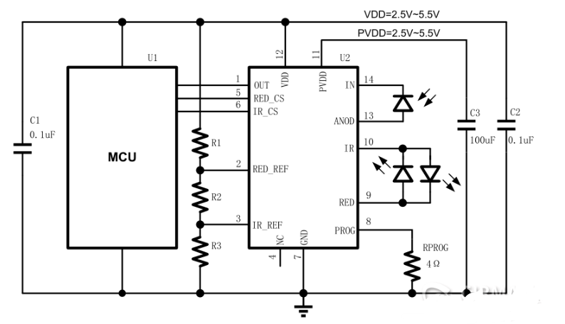
TS9514 application schematic
Figure 1-3 shows the TS9514 application. The IR and RED pins of TS9514 connect to the red and infrared LEDs. The two LEDs are inverse-parallel. IN and ANOD connect to a photodiode. PROG connects to a current-sense resistor. RED_REF and IR_REF set the drive currents for the red and infrared LEDs; these pins require a voltage derived from the R1, R2, R3 divider. The MCU controls RED_CS and IR_CS to select red or infrared drive. OUT connects to the MCU and outputs a frequency proportional to the photodiode current. PVDD supplies the pulsed LED current; it is not recommended to share PVDD and VDD, and a large decoupling capacitor should be placed near the PVDD pin.
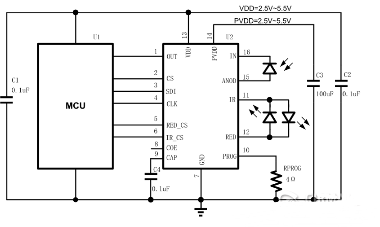
TS9517 application schematic
Figure 1-4 shows the TS9517 application. Unlike the TS9514, the TS9517 supports digital dimming. The MCU controls an internal 7-bit DAC via an SPI bus formed by CS, SDI, and SCK to adjust LED intensity. TS9517 also provides a COE pin for hardware ambient-light cancellation, which can be toggled by an MCU GPIO; if the feature is unused, tie COE to ground.