Mobile phones depend on robust RF signal reception and transmission for reliable connectivity. Weak or fluctuating signals often trace back to challenges in the phone's printed circuit board (PCB) design, antenna integration, RF front-end circuitry, and overall electromagnetic compatibility (EMC). At Aivon, we specialize in high-performance PCBs that power modern telecommunications devices, where even minor layout or material decisions can dramatically affect signal integrity in real-world conditions.
Core Factors Affecting Mobile Signal Strength
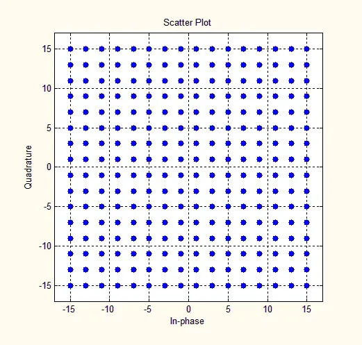
Signal strength, typically measured as RSRP (Reference Signal Received Power) in dBm, results from the complex interaction between base station infrastructure and the mobile device's hardware.
Distance from Base Stations and Propagation Loss
As distance from a cell tower increases, free-space path loss rises, forcing the device to increase transmit power or rely on weaker received signals. PCB designers must optimize the RF chain - including power amplifiers, low-noise amplifiers (LNAs), and filters - to maintain performance across wide dynamic ranges. High copper thickness, controlled impedance traces, and low-loss laminates (such as Rogers or high-Tg FR4) help minimize insertion loss in these critical paths.

Obstacles and Environmental Attenuation
Buildings, vehicles, glass, and even human bodies attenuate RF signals. In dense urban environments or indoors (basements, elevators), signals undergo reflection, diffraction, and absorption. The phone's PCB antenna system must handle multipath fading effectively. This requires careful antenna tuning, ground plane design, and sometimes multiple antennas with diversity switching - all of which depend on precise multilayer PCB stack-ups and via technology.

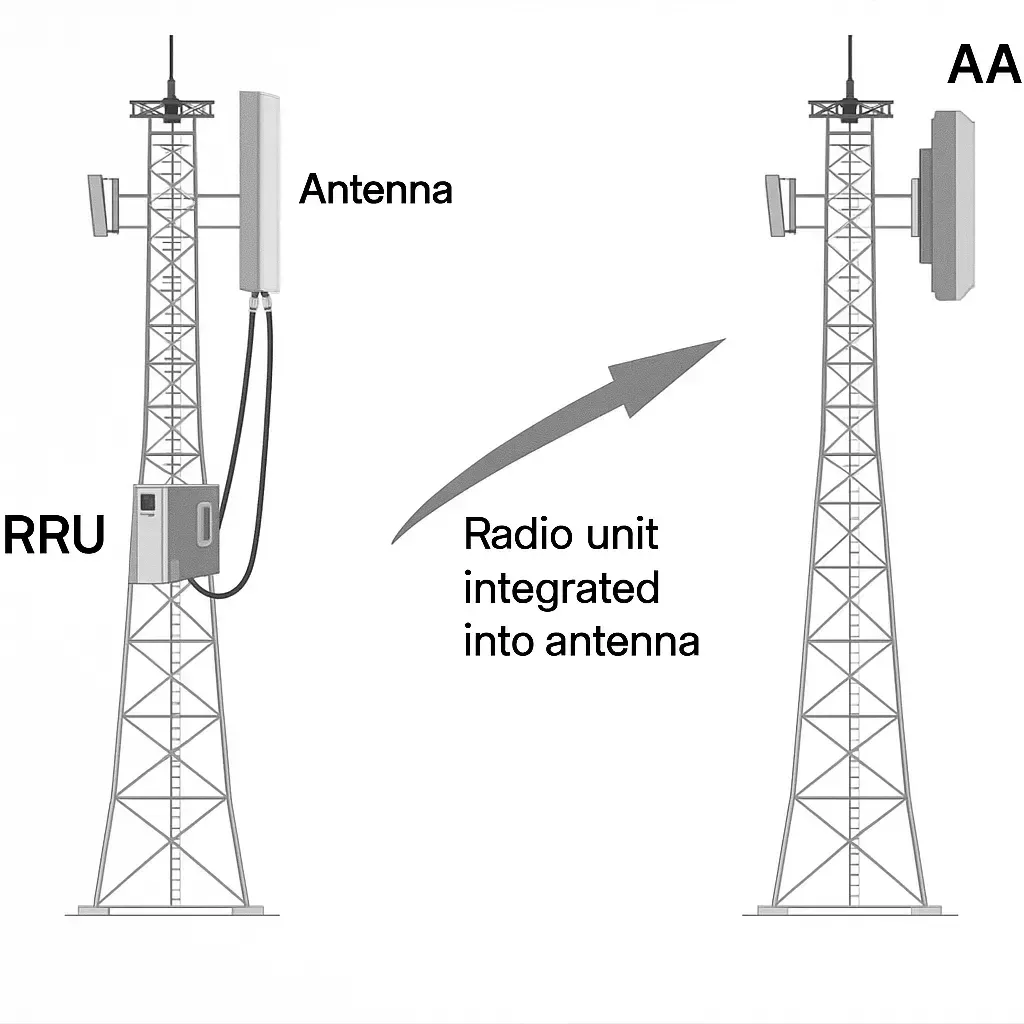
Base Station Antenna Configuration
Base station antenna azimuth and downtilt directly influence coverage. Poor alignment can create coverage holes. While device designers cannot control towers, they can build phones with superior RF sensitivity through optimized PCB layouts that reduce noise coupling into the receiver chain.
The Critical Role of Baseband and RF PCB Design
The baseband chipset processes radio signals, acting as the "translator" between RF and digital domains. Inefficient baseband performance or poor integration with the RF front-end often manifests as weak perceived signals.
Key PCB considerations include:
- Impedance Control: 50 ohms transmission lines for RF traces to prevent reflections and signal loss.
- Layer Stack-Up: Strategic placement of RF layers with solid ground planes to minimize crosstalk and EMI.
- Component Placement: Separating high-power PA sections from sensitive receivers to avoid desensitization.
- Thermal Management: High-current RF sections generate heat. Proper copper pours, thermal vias, and material selection prevent performance degradation from temperature rise.
Why Signal Bars Fluctuate: Network Interaction and Modem Stability
Signal bars do not directly equal raw signal strength. They reflect the device's reporting of radio conditions to the network, which then selects bands and technologies.
Fluctuations often stem from:
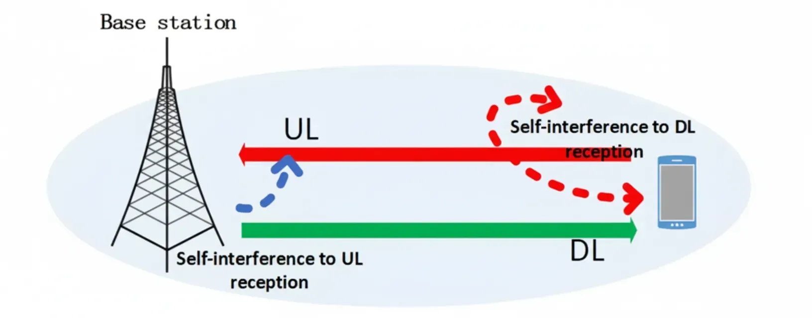
- 4G/5G Handover and Bearer Management: Frequent switching between technologies can trigger modem instability. PCB-level power integrity (PI) becomes crucial here - voltage droops or noise on power rails during mode changes can contribute to crashes.
- Software-Hardware Interactions: Configuration errors (such as incorrect phone number settings) can cause repeated SIP bearer reactivation, leading to visible bar flickering. While this appears software-related, it stresses the modem and RF subsystems, highlighting the need for robust PCB designs that support stable operation under repeated state changes.
- Modem Crashes: Certain 4G/5G interaction scenarios have triggered baseband crashes in specific devices. High-quality PCBs with excellent signal integrity and decoupling help mitigate hardware contributions to such instabilities.
Shielding and Electromagnetic Interference (EMI/EMC)
Can Aluminum Foil Block Mobile Signals?
Yes. Household aluminum foil creates an effective Faraday cage for mobile frequencies. At ~2.5 GHz, skin depth in aluminum is only about 1.6 micrometers. Standard foil (~50 micrometers thick) provides dozens of skin depths, reflecting most energy and absorbing the rest. This demonstrates the principles of RF shielding used in actual phone design.
In PCB manufacturing, engineers apply similar concepts through:
- Metal Shields/Cans: Over critical RF sections.
- Ground Planes and Via Stitching: Creating continuous shielding barriers.
- Multilayer Construction: Burying sensitive traces between ground layers.
- EMI Mitigation: Careful routing to avoid slots in ground planes that act as antennas for interference.
PCB Manufacturing Solutions for Superior Mobile RF Performance
To combat weak and fluctuating signals, Aivon recommends:
- High-Frequency PCB: Low Dk/Df laminates for reduced dielectric loss in RF paths.
- HDI and Microvia Technology: For compact, high-density routing in slim devices.
- Impedance Tolerances: Tight control (plus or minus 5-10%) for consistent RF performance across production.
- Surface Finishes: ENIG or other low-loss finishes to maintain signal quality at connectors and antennas.
- Testing and Validation: RF testing, signal integrity analysis, and thermal profiling during manufacturing.
Practical Tips for Users and Engineers
- Check actual RSRP values (3001#12345# on iOS or Settings on Android) rather than relying on bars.
- Position phones away from large metal objects when possible.
- For device makers: Invest in collaborative PCB design that optimizes antenna efficiency, power integrity, and shielding from the schematic stage through volume manufacturing.
Strong mobile connectivity ultimately depends on excellence in PCB engineering. From material selection and stack-up design to precise fabrication and assembly, every decision influences how well a device performs in challenging RF environments. At Aivon, we help electronics manufacturers build more reliable mobile communication devices through advanced PCB solutions tailored to RF and high-speed requirements.