What Makes Up a Battery Charger Printed Circuit Board?
For those new to the world of electronics, the internal workings of a battery charger can seem complex. However, at its core, a battery charger printed circuit board (PCB) is a meticulously arranged collection of essential electronic components. These parts—resistors, capacitors, diodes, transistors, and integrated circuits—each perform specific tasks to ensure batteries are charged both safely and effectively. This guide aims to demystify these components, outlining their individual roles within a charger and offering a foundational understanding of PCB design for budding electronics enthusiasts.
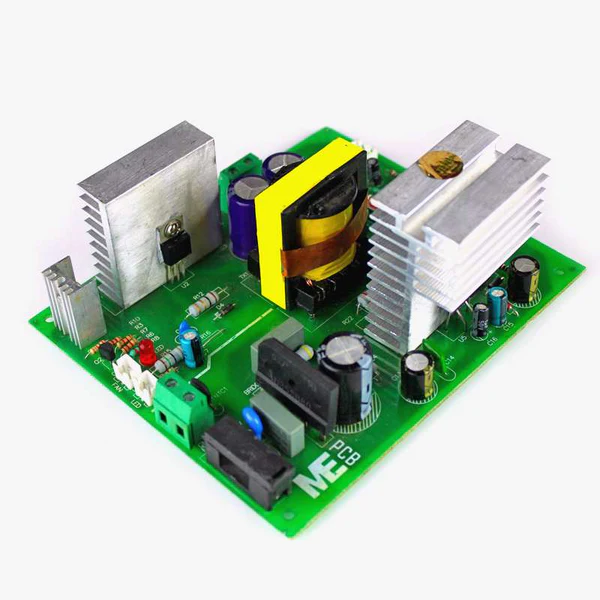
A battery charger PCB serves as the central control unit for any charging device, whether it's powering a smartphone or a portable battery pack. It's a compact board where various electronic elements collaborate to process incoming power, regulate electrical flow, and deliver the precise current and voltage a battery needs for a secure charge. Grasping the function of each component on this board is a vital step for anyone embarking on their journey into beginner electronics.
Why Do Specific Components Matter in Battery Chargers?
Individual components mounted on a printed circuit board are what enable an electronic device to function, and in a battery charger, their roles are critical. These parts meticulously manage power distribution, safeguard the circuit from damage, and prevent issues like overcharging or short-circuiting a battery. For anyone beginning in electronics, familiarizing oneself with these elements is the initial step toward either creating new circuits or troubleshooting existing ones.
The combined efforts of these components dictate how a battery charger operates, handling tasks such as converting AC input to DC output, stepping down voltages, and limiting current to protect devices. For example, a typical charger might convert standard wall current (e.g., 120V AC) into a safe, usable 5V DC at 1-2 amps, suitable for a smartphone. Without this harmonious interplay, a charger could malfunction or even pose serious safety risks, such as overheating or electrical damage.
Suggested Reading: Key Considerations for Selecting Components in High-Reliability Electronics
Key Components of a Battery Charger PCB Explained
Let's delve into the fundamental components found on a battery charger PCB. We will examine resistors, capacitors, diodes, transistors, and integrated circuits, detailing their functions and emphasizing why their understanding is crucial for newcomers to electronics.
Resistors: Regulating Electrical Flow
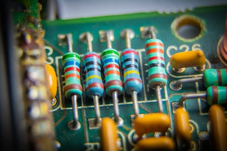
Resistors are among the most straightforward yet indispensable components within a battery charger PCB. Their primary purpose is to restrict the amount of current traversing a circuit, thereby shielding other delicate components from potential harm. Within a charger, resistors are instrumental in fine-tuning the charging current to match the specific requirements of the battery. For instance, a resistor might reduce excess voltage, ensuring that a 3.7V lithium-ion battery receives appropriate power from a 5V input source, preventing it from being overstressed.
The resistance of these components is quantified in ohms (Ω), with their specific value dictating the degree to which they impede current. Common resistor values in chargers might range from 220Ω to 1kΩ, depending on the circuit's design. Beginners can learn to identify resistor values by interpreting the color bands typically marked on their bodies using widely available charts.
Capacitors: Energy Storage and Voltage Smoothing
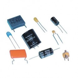
Capacitors function as temporary electrical storage units, absorbing and then releasing energy as required—much like miniature batteries. On a battery charger PCB, they play a crucial role in stabilizing voltage fluctuations, delivering a consistent and ripple-free power output to the battery. This function is particularly vital in chargers that convert alternating current (AC) into direct current (DC), as this conversion process can introduce undesirable voltage "ripple" or inconsistencies. A capacitor, often rated in microfarads (μF)—such as a 10μF or 100μF—effectively filters this ripple, ensuring a steady charge.
Various types of capacitors exist, including ceramic and electrolytic, each optimized for different applications. Electrolytic capacitors, for example, are frequently utilized in the power supply sections of chargers due to their ability to store larger amounts of charge.
Diodes: Ensuring Unidirectional Current
Diodes are electronic components designed to permit electrical current to flow in one direction exclusively, analogous to a one-way valve. In a battery charger, diodes are indispensable for the rectification process, which converts incoming AC power into usable DC power. They also provide crucial protection against reverse current flow, safeguarding the battery from discharging back into the charger circuit if the power supply is interrupted. Schottky diodes are a popular choice in chargers dueishing to their low forward voltage drop (typically around 0.3V) and rapid switching capabilities, which enhance overall efficiency.
Consider a 5V charger circuit: a diode would ensure that current is directed solely towards the battery, thereby protecting the entire system from potential damage should the input power source be disconnected. It is essential for beginners to understand that diodes possess polarity and must be correctly oriented during installation to function as intended.
Transistors: Managing Switching and Amplification
Transistors are highly adaptable components that serve dual roles as electronic switches or signal amplifiers within a battery charger PCB. As switches, they control the activation and deactivation of the charging current, often integrated into circuits that manage distinct charging phases (e.g., trickle charging versus full charge cutoff). In their amplification capacity, transistors can boost weak electrical signals, ensuring the charger's proper and reliable operation.
Metal-Oxide-Semiconductor Field-Effect Transistors (MOSFETs) are commonly found in chargers, prized for their efficiency in managing high-current applications. For instance, a transistor might be responsible for seamlessly transitioning between a 1-amp slow charge mode and a 2-amp fast charge mode, depending on the battery's current state and requirements. Their capacity to handle significant power with minimal energy loss (with some MOSFETs exhibiting resistance as low as 0.01Ω) makes them indispensable in contemporary charger designs.
Integrated Circuits (ICs): The Controller of the Charger
Integrated circuits, or ICs, are frequently referred to as the "brains" of a battery charger PCB. These minuscule chips incorporate thousands of miniaturized components and are tasked with executing intricate operations such as precise voltage regulation, sophisticated charge monitoring, and the implementation of crucial safety protocols. Within a charger, an IC might manage the entire charging profile for a lithium-ion battery, ensuring a multi-stage process (e.g., constant current followed by constant voltage) to optimize battery lifespan and performance.
A typical charger IC might be programmed to deliver a precise 4.2V output for a single-cell lithium battery, automatically halting the charging process once the battery reaches its full capacity. These specialized chips often feature integrated safeguards against overvoltage, overcurrent, and overheating—protections that are absolutely critical for safe and reliable operation. For beginners, while ICs may appear daunting, it’s helpful to view them as pre-programmed, compact controllers that significantly simplify complex circuit design.
How Charger Components Cooperate for Optimal Charging
Having explored the individual functions of resistors, capacitors, diodes, transistors, and integrated circuits, let's now understand their collective operation within a battery charger PCB. Consider a basic USB charger designed to deliver 5V at 1A to a connected device. Here’s a simplified illustration of their synergistic workflow:
Input Stage: Diodes convert the incoming alternating current (AC) power—if from a wall adapter—into direct current (DC). Simultaneously, capacitors work to smooth out any voltage fluctuations, ensuring a stable DC supply.
Regulation Stage: An integrated circuit (IC) meticulously monitors and fine-tunes the output voltage and current. Resistors are precisely set to define current limits, while transistors selectively switch power pathways as dictated by the IC.
Output Stage: Diodes are strategically placed to prevent any reverse current flow, guaranteeing that the battery receives a consistent and damage-free charge.
This synchronized effort is vital for ensuring that a battery charges both efficiently and safely, free from the risks of damage. As a practical example, a 5V, 2A charger might employ a 1kΩ resistor to precisely limit current, a 47μF capacitor to effectively stabilize voltage, a Schottky diode for its low-loss current direction, a MOSFET for efficient power switching, and a central IC to meticulously oversee the entire charging sequence.
Addressing Common Challenges with Charger PCBs for Novices
For those new to electronics, engaging with battery charger PCBs can present several learning curves. Here are some typical hurdles encountered by beginners and practical advice on how to navigate them effectively:
Component Polarity: Many components, such as diodes and certain capacitors (e.g., electrolytic), are sensitive to polarity, meaning they have distinct positive and negative terminals. Incorrect installation can lead to immediate circuit damage. Always meticulously verify component markings before soldering.
Thermal Management: Transistors and integrated circuits, especially when handling higher currents (e.g., exceeding 2A), are prone to generating significant heat. It’s crucial to incorporate heat sinks or ensure that the PCB layout is designed to facilitate adequate cooling, preventing overheating and potential component failure.
Component Ratings: Employing a capacitor or resistor with an unsuitable rating (e.g., using a 16V capacitor in a circuit that operates at 20V) can inevitably lead to component malfunction or complete failure. Always double-check critical specifications such as voltage limits, current capacities, and power dissipation ratings.
Practical Advice for Newcomers to Battery Charger PCBs
If you are just starting out in beginner electronics and are keen to experiment with battery charger PCBs, here are some actionable tips to help you get started confidently:
Embrace Simplicity: Begin with a straightforward charger design, perhaps for a single-cell battery, utilizing a minimal number of components. This approach allows you to focus on understanding each part's individual function without being overwhelmed.
Utilize a Multimeter: This indispensable tool will allow you to measure voltage and current at various points within your circuit. This hands-on experience will provide concrete insights into how different components influence the electrical flow. For instance, you can measure the voltage drop across a resistor, which might typically range from 0.5V to 1V in low-power applications.
Prioritize Safety: Always ensure that the power supply is disconnected before commencing any work on a quick turn PCB. Make it a strict habit to avoid handling live circuits to prevent electrical shocks or accidental short circuits.
Master Schematic Reading: Schematics are essentially the architectural blueprints for PCBs. They illustrate how components, such as resistors (often depicted as zigzag lines) and capacitors (represented by parallel lines), are interconnected. Developing this skill is fundamental for accurately constructing or efficiently troubleshooting charger circuits.
Concluding Thoughts: Expanding Your Electronics Expertise
A fundamental grasp of the components that comprise a battery charger PCB—including resistors, capacitors, diodes, transistors, and integrated circuits—is an essential stepping stone for anyone venturing into the field of beginner electronics. Each of these parts fulfills a distinct and vital role, collectively ensuring that a charger operates both safely and with peak efficiency, from precisely controlling current to meticulously stabilizing voltage. By understanding how these components interact and perform their functions, you gain the knowledge necessary to design, assemble, or repair charging circuits for a wide array of electronic devices.
As your journey in electronics progresses, remember that persistent practice and patience are key determinants of success. Initiate your learning with smaller, manageable projects, pay close attention to the specific ratings and characteristics of each component, and commit to continuous learning about the intricacies of PCB design. Armed with this comprehensive guide explaining PCB components, you now possess a robust foundation to explore the captivating domain of battery chargers and many other electronic applications beyond.