1. Introduction to Rigid-Flex Technology
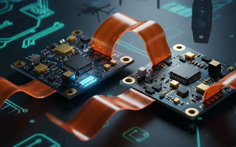
In the rapidly evolving landscape of electronic design, the demand for smaller, lighter, and more durable devices has led to the rise of Rigid-Flex PCB technology. By combining the best of both worlds—the stability of rigid PCBs and the versatility of flexible circuits—this hybrid solution allows engineers to design into three dimensions. Unlike traditional cabling and connector-based systems, rigid-flex boards offer a streamlined architecture that saves space while enhancing signal integrity.
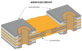
2. How Rigid-Flex PCBs Work: Materials and Construction
Deep Dive: Adhesiveless Base Materials
The foundation of a high-quality Rigid-Flex PCB lies in its base materials. Historically, manufacturers used acrylic or modified epoxy adhesives to bond the flexible polyimide to the copper foil. However, modern high-performance applications have shifted toward adhesiveless base materials.
Adhesiveless laminates eliminate the need for an additional adhesive layer, usually by casting the polyimide directly onto the copper or using a specialized thermal bonding process. The technical advantages are profound. First, without the adhesive layer, the total thickness of the flex section is reduced, which significantly improves the bend radius and flexibility—crucial for tight enclosures. Second, adhesives often have a high coefficient of thermal expansion (CTE) and high moisture absorption. By removing them, the board achieves superior thermal stability and reliability during lead-free soldering processes. For high-speed applications, adhesiveless materials offer a lower dielectric constant (Dk) and loss tangent (Df), ensuring that signal degradation is kept to an absolute minimum.
The Role of Polyimide and Copper Types
The flexible core typically uses Polyimide (PI), a thermoset polymer known for its exceptional heat resistance and mechanical toughness. In Rigid-Flex construction, the choice of copper foil is equally critical. While Electro-Deposited (ED) copper is standard for rigid boards, Rigid-Flex designs often utilize Rolled Annealed (RA) copper. RA copper undergoes a specialized rolling process that aligns its grain structure horizontally, making it far more resistant to fatigue and cracking during repeated bending—a prerequisite for dynamic applications.
3. Key Advantages of Rigid-Flex Solutions
Space and Weight Reduction: Eliminates the need for bulky wire harnesses and connectors, often reducing total weight by up to 60%.
Enhanced Reliability: Fewer solder joints and connectors mean fewer potential failure points under mechanical stress or vibration.
Superior Signal Integrity: Continuous copper paths across the flex and rigid sections minimize impedance mismatches and EMI.
Dynamic Flexibility: Capable of withstanding millions of flex cycles in moving parts.
4. Strategic Applications: Industry Focus
Rigid-Flex technology is not a "one-size-fits-all" solution; its implementation varies significantly across high-stakes industries. Below, we explore how this technology solves specific challenges in medical, wearable, and aerospace sectors.
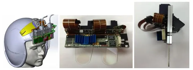
A. Revolutionizing Healthcare with Precision
In the medical field, the drive toward minimally invasive procedures and portable diagnostic tools has made rigid-flex circuitry indispensable. By integrating complex electronics into tiny, ergonomic shapes, manufacturers can create devices that were previously impossible. As explored in our dedicated guide on Rigid-Flex PCB applications in medical devices, this technology is enabling miniaturized and flexible innovations in surgical tools and diagnostic imaging, allowing for higher component density within biocompatible constraints.
B. The Backbone of Next-Gen Wearables
Wearable technology demands a unique balance of durability and comfort. Because these devices are worn on the body, they must endure constant movement and moisture while maintaining high-performance data tracking. Rigid-flex technology serves as the ultimate solution for complex wearable health monitors, providing the necessary mechanical endurance for biometric tracking and ergonomic design in smartwatches and continuous glucose monitors.
C. Aerospace and Avionics: Reliability in Extreme Conditions
In the aerospace sector, failure is not an option. Rigid-flex boards are designed to withstand extreme vibrations, thermal fluctuations, and G-forces while occupying the smallest possible footprint in a cockpit or satellite. For high-reliability environments, Rigid-Flex PCBs in avionics offer a flexible solution for complex systems, significantly reducing weight and enhancing connection stability in space-constrained aerospace electronics.

5. Design Considerations for Complex Rigid-Flex Systems
Designing a Rigid-Flex PCB requires a shift from 2D logic to 3D mechanical engineering. To ensure high reliability, engineers must prioritize these five design pillars:
Strategic Stiffener Selection: In the medical area, stiffeners (FR4 or Polyimide) are essential. They provide localized mechanical support for SMT components in the flex areas, preventing solder joint stress while maintaining a slim overall profile.
Optimizing Bend Radius and Geometry: For wearable health monitors, the bend radius is critical. Designers must follow the 10x (static) or 20x (dynamic) thickness rule and use curved traces instead of sharp angles to distribute mechanical stress evenly and prevent copper fatigue during body movement.
Hatched Ground Planes for Flexibility: To maintain a flexible solution for complex systems in avionics, engineers use hatched (cross-hatched) copper planes rather than solid ones. This provides necessary EMI shielding and impedance control without making the flexible section too rigid or brittle.
Reinforced Pad and Via Placement: Mechanical movement can peel pads off the flex substrate. Implementing "teardrop" shapes at trace-to-pad junctions and adding anchoring spurs are vital techniques to secure connections in high-vibration aerospace and wearable environments.
Transition Zone Management: The interface where the rigid board meets the flex circuit is a high-stress area. Designers must keep vias and component pads at least 50 mils away from this "bend line" to ensure the ultimate solution for complex wearable health monitors remains durable under constant use.
6. The Manufacturing Process: Precision and Challenges
The production of rigid-flex boards is more labor-intensive than standard PCBs. It involves specialized lamination processes, controlled depth drilling, and plasma etching to ensure clean connections between the different material layers. Quality control, including automated optical inspection (AOI) and flying probe testing, is critical to maintain high yields.
7. Future Trends in Rigid-Flex Integration
As we move toward 5G, IoT, and advanced AI-driven hardware, the role of Rigid-Flex PCBs will only grow. We are seeing a trend toward Ultra-HDI (High-Density Interconnect) rigid-flex boards, which use even finer line widths and spaces (sub-25 microns) to accommodate the next generation of micro-chips. Additionally, the integration of embedded components—where resistors and capacitors are built directly into the inner layers—is helping to push the boundaries of miniaturization even further.
8. Conclusion
Rigid-flex PCBs are no longer a niche technology—they are a core enabler of modern electronic innovation. By combining mechanical flexibility with electrical reliability, they provide unmatched advantages in applications where traditional PCBs fall short.
From avionics systems requiring vibration resistance, to medical devices demanding biocompatibility, and wearables pushing the limits of miniaturization, rigid-flex PCBs are redefining what is possible in electronic design.
By understanding key application domains and leveraging targeted design strategies, engineers can fully unlock the potential of rigid-flex PCB technology in next-generation products.
FAQs
Q1: Why should I choose Rigid-Flex PCBs over traditional cable-connected boards?
A1: Rigid-Flex PCBs offer significant advantages in terms of reliability and space efficiency. By eliminating bulky connectors and wire harnesses, you reduce the overall weight and eliminate potential failure points like loose connections or cold solder joints. This makes them a flexible solution for complex systems where signal integrity and mechanical durability are non-negotiable, particularly in high-vibration or mission-critical environments.
Q2: How does Rigid-Flex technology support miniaturization in medical devices?
A2: In the medical field, space is at a premium. Rigid-Flex circuitry allows engineers to fold the PCB into 3D shapes, fitting complex electronics into tiny, ergonomic housings. This is a key factor in enabling miniaturized and flexible innovations such as swallowable cameras, advanced endoscopes, and portable diagnostic tools, where traditional rigid boards would be too cumbersome.
Q3: Can Rigid-Flex PCBs withstand the extreme environments of the avionics industry?
A3: Yes. In aerospace applications, electronics must endure extreme thermal cycling, high G-forces, and intense vibration. Rigid-Flex PCBs in avionics are designed with robust materials like Polyimide and high-TG FR4 to ensure long-term stability. By reducing the number of interconnects, they provide a much higher MTBF (Mean Time Between Failures) than standard wiring solutions.