Introduction
Buzzers serve as essential components in automotive electronics, delivering immediate auditory feedback to drivers and passengers. These devices produce distinct tones for car buzzer alerts such as seatbelt reminders, parking sensor warnings, and low fuel indicators. In modern vehicles, automotive buzzer systems integrate seamlessly with electronic control units to enhance safety and user experience. Reliability becomes paramount because vehicles operate in demanding environments filled with constant vibrations, temperature fluctuations, and moisture exposure. Engineers must prioritize buzzer reliability in vehicles to prevent failures that could compromise critical alerts. This article explores applications, technical principles, and key reliability requirements for these components.
What Are Automotive Buzzer Systems and Why Do They Matter?
Automotive buzzer systems consist of electroacoustic transducers that convert electrical signals into sound waves for alerting purposes. They fall into two primary categories: piezoelectric buzzers and magnetic buzzers. Piezoelectric types use crystal deformation to generate high sound pressure levels, making them suitable for penetrating noises in noisy cabins. Magnetic buzzers rely on electromagnetic coils to vibrate a diaphragm, offering simpler drive circuits at lower voltages. These systems matter because they provide redundant safety cues beyond visual displays, especially during high-speed driving or distractions.
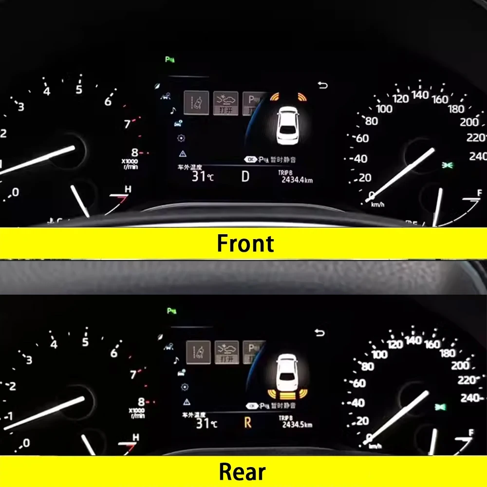
Car buzzer alerts play a vital role in advanced driver assistance systems and infotainment. For instance, reverse parking aids use pulsed tones to indicate proximity to obstacles, helping prevent collisions. Seatbelt warnings escalate in volume and pattern to ensure compliance, while door-ajar signals remind occupants to secure entry points. Without reliable buzzers, drivers might miss these cues, leading to safety risks or regulatory non-compliance. Procurement teams and engineers select these components based on integration with vehicle CAN bus networks and power supplies typically ranging from 12V systems.
The relevance extends to electric and autonomous vehicles, where auditory feedback supports haptic and visual interfaces. Buzzers must align with overall system architecture, including PCB mounting for compact dashboards or under-seat modules. Failure rates directly impact warranty costs and brand reputation in the competitive automotive sector.
Technical Principles of Buzzers in Automotive Applications
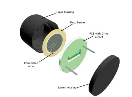
Piezoelectric buzzers operate on the piezoelectric effect, where applied voltage causes a ceramic disk to expand or contract rapidly. This mechanical vibration pushes air to create sound waves at resonant frequencies optimized for human hearing. Engineers drive these with oscillating signals from microcontrollers to produce continuous tones, pulses, or sweeps. Passive versions require external oscillators, while active ones include built-in circuits for simpler integration into automotive buzzer systems.
Magnetic buzzers function through an electromagnet that attracts a ferrous diaphragm when current flows through a coil. The diaphragm snaps back upon current reversal, generating audible clicks or tones. These require higher current but lower voltage compared to piezo types, suiting 12V automotive batteries directly. Frequency control comes from the drive signal's pulse width or rate, allowing patterns like fast beeps for urgent car buzzer alerts.
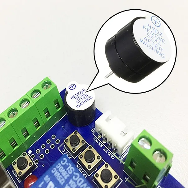
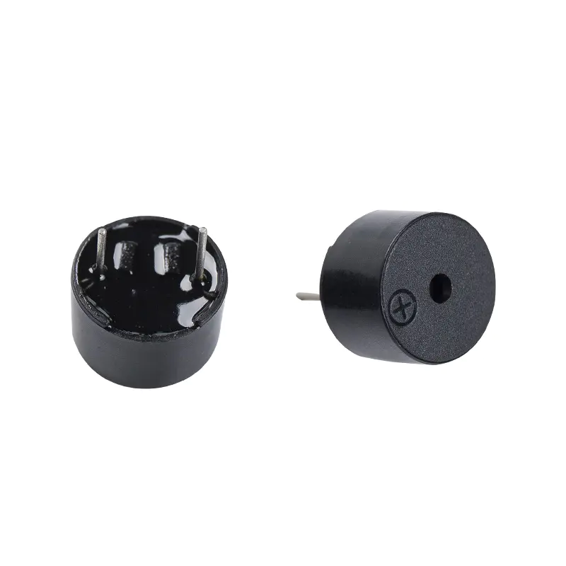
Both types mount via pins or SMD pads onto PCBs, where solder joints transfer vibrations from the vehicle chassis. Sound output depends on enclosure design, which amplifies resonance while sealing against dust ingress. In vehicles, buzzers often pair with amplifiers for volume control, ensuring audibility over engine noise or road rumble.
Reliability Requirements for Buzzers in Vehicles
Buzzer reliability in vehicles hinges on enduring mechanical stresses from road irregularities, engine harmonics, and suspension movements. Vibration induces fatigue in solder joints, leading to intermittent contacts or total failure. Components must resist accelerations across broad frequency spectra without altering tone quality or ceasing operation. Thermal cycling exacerbates issues by expanding materials at different rates, potentially cracking adhesives or diaphragms.
Humidity and dust pose corrosion risks to contacts and coils, demanding sealed housings with IP ratings suitable for under-hood or cabin exposure. Electrical reliability involves surviving voltage transients from load dumps or starts, preventing insulation breakdown. Automotive component standards guide qualification, ensuring parts meet operational life targets exceeding 10 years or millions of cycles.
Vibration resistance stands out as a core requirement, with tests simulating real-world profiles. ISO 16750-3 outlines mechanical load testing for electrical equipment in road vehicles, including random and sinusoidal vibrations. This standard helps engineers verify buzzer vibration resistance under profiles mimicking passenger car or truck dynamics. Compliance reduces field failures, maintaining consistent car buzzer alerts.
Temperature extremes from -40°C to over 100°C in engine bays test material stability. Piezo ceramics risk depolarization at high temps, while magnetic coils may demagnetize. Combined stresses accelerate wear, so sequential testing sequences validate endurance.
IEC 60068-2-6 specifies sinusoidal vibration methods, providing severity levels for component qualification. These tests sweep frequencies to identify resonances where amplification could cause damage. Engineers analyze frequency response curves post-test to confirm no degradation in sound pressure or electrical parameters.
Best Practices for Selecting and Integrating Automotive Buzzers
Select buzzers rated for automotive environments, prioritizing those with proven vibration resistance. Review datasheets for test reports aligned with automotive component standards like ISO 16750-3. Prefer SMD packages for automated assembly on high-volume PCBs, ensuring pad layouts minimize stress concentrations. Active buzzers simplify PCB real estate by embedding oscillators, reducing external component count.
Mounting strategies enhance reliability. Secure buzzers with epoxy potting or clips to dampen chassis vibrations before reaching solder joints. PCB design incorporates anchor points and wider traces under the buzzer to distribute loads. Avoid placing near high-heat sources; thermal vias aid dissipation if needed.
Testing protocols mirror production stresses. Perform in-circuit functional tests post-assembly, followed by environmental chambers for vibration and thermal shock. Use accelerometers to monitor during shaker runs per IEC 60068-2-6 guidelines. Accelerated life testing extrapolates field performance, identifying weak designs early.
Integration with ECUs demands low EMI, as buzzer drive currents can radiate noise. Ferrite beads on supply lines filter harmonics. Firmware patterns optimize alert escalation, starting soft and ramping for attention without annoyance.
IPC-A-610 provides acceptability criteria for soldered assemblies, ensuring joint integrity under vibration. Visual and X-ray inspections catch voids or cracks pre-shipment. These practices yield robust automotive buzzer systems with minimal returns.
Troubleshooting Common Issues in Automotive Buzzer Systems
Intermittent or absent tones often trace to loose solder joints from vibration fatigue. Inspect under magnification for cracks, reflowing with automotive-grade paste if needed. Measure resistance across pads; high values indicate opens. Power supply glitches from battery transients cause dropouts, so add TVS diodes for clamping.
Distorted sounds suggest diaphragm damage or resonance shifts. Vibration history correlates with this; replace with higher-rated parts. Noisy drive signals from microcontroller PWM artifacts require low-pass filtering. Test in isolation by direct-driving with a signal generator to isolate PCB issues.
Water ingress mutes output via corrosion. Ultrasonic cleaning followed by conformal coating restores function temporarily, but redesign sealing. Overheating melts adhesives; thermal profiling during integration prevents recurrence. Systematic logging of failure modes builds reliability data for iterative improvements.
Environmental mismatches cause bulk failures. Cross-reference specs against vehicle zones per ISO 16750-3. Field returns analysis guides supplier audits, focusing on buzzer vibration resistance.
Conclusion
Automotive buzzer systems deliver critical car buzzer alerts that bolster vehicle safety through reliable auditory cues. Understanding piezo and magnetic principles aids selection for specific applications like parking aids or warnings. Reliability demands focus on vibration resistance, guided by standards such as ISO 16750-3, IEC 60068-2-6, and IPC-A-610. Best practices in design, mounting, and testing ensure long-term performance amid harsh conditions. Engineers troubleshooting issues like joint fatigue maintain system integrity. Prioritizing these elements optimizes buzzer reliability in vehicles for enhanced automotive electronics.
FAQs
Q1: What standards ensure buzzer vibration resistance in automotive applications?
A1: ISO 16750-3 defines mechanical load tests, including vibration profiles for road vehicles, simulating real-world stresses on components like buzzers. IEC 60068-2-6 complements with sinusoidal sweeps to detect resonances. Compliance verifies automotive buzzer systems withstand engine and road inputs without failure. Engineers use these for qualification, reducing field issues.
Q2: How do car buzzer alerts integrate with vehicle safety systems?
A2: Car buzzer alerts connect via ECUs, using CAN protocols for timed patterns in seatbelt or parking functions. Active buzzers simplify drive circuits on PCBs. Vibration-resistant mounting preserves signal integrity. Testing per automotive component standards confirms reliability under operation.
Q3: Why is vibration a key factor in buzzer reliability in vehicles?
A3: Vibration fatigues solder joints and diaphragms, causing intermittent car buzzer alerts or total loss. Road and engine sources span wide frequencies, demanding robust designs. Standards like ISO 16750-3 guide testing for endurance. Proper PCB anchoring and potting mitigate risks effectively.
Q4: What best practices improve automotive buzzer systems longevity?
A4: Choose sealed, automotive-grade buzzers with IEC 60068-2-6 vibration ratings. Epoxy mounting and stress-relief on PCBs distribute loads. Sequential environmental testing identifies weaknesses. Firmware optimizes tones for clarity without overload.
References
ISO 16750-3 — Road vehicles. Environmental conditions and testing for electrical and electronic equipment. Part 3: Mechanical loads. ISO.
IEC 60068-2-6 — Environmental testing. Part 2-6: Tests. Test Fc: Vibration (sinusoidal). IEC.
IPC-A-610 — Acceptability of Electronic Assemblies. IPC.