Introduction
Selective soldering has become a critical process in modern electronics assembly, especially for mixed-technology printed circuit boards (PCBs) that combine surface-mount and through-hole components. Unlike traditional wave soldering, which applies solder across an entire board, selective soldering targets specific areas, minimizing thermal stress on sensitive components. This precision is vital for electrical engineers working on complex assemblies where reliability and quality are paramount. In this article, we explore various selective soldering systems, focusing on laser selective soldering systems, mass selective dip solder fountains, and selective aperture tooling over wave solder. Each method offers unique advantages and challenges, impacting production efficiency and product integrity. By understanding these systems, engineers can make informed decisions for their specific assembly needs, ensuring compliance with industry standards and optimal performance.
What Is Selective Soldering and Why It Matters
Selective soldering refers to a specialized process used in PCB assembly to solder specific components or areas on a board while avoiding others. This technique is essential in scenarios where mixed assemblies feature components sensitive to high temperatures or where precise solder application is required. Traditional methods like wave soldering can expose entire boards to molten solder, risking damage to delicate parts. Selective soldering mitigates this by focusing heat and solder only where needed, preserving component integrity.
The importance of selective soldering lies in its ability to support the miniaturization trend in electronics. As devices become smaller and more complex, engineers must ensure reliable connections without compromising adjacent components. This process also enhances manufacturing flexibility, allowing for tailored solutions in high-mix, low-volume production environments. For electrical engineers, choosing the right selective soldering system directly influences assembly quality, yield rates, and overall project success.
Related Reading: Achieving Precision in PCB Assembly: A Guide to Selective Soldering
Technical Principles of Selective Soldering Systems
Laser Selective Soldering System
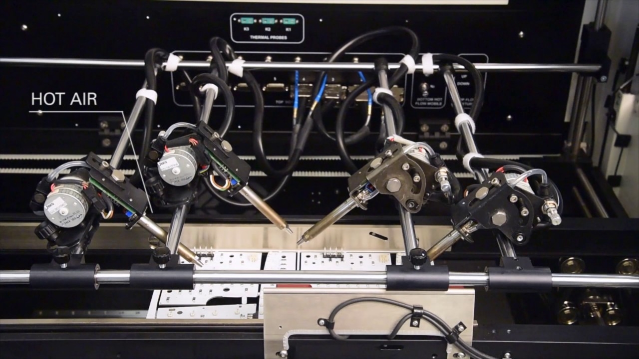
Laser selective soldering uses a focused beam of laser energy to heat specific solder joints on a PCB. This method delivers precise thermal energy to individual points, melting solder paste or wire without affecting surrounding areas. The laser's accuracy allows for soldering in tight spaces, making it ideal for densely populated boards. The process is typically toolless, reducing setup times and costs associated with custom fixtures.
This system operates by directing a laser beam, often in the infrared spectrum, onto the target area. The energy absorbed by the solder material causes it to melt and form a joint. Control systems ensure the laser's intensity and duration are optimized to prevent overheating. This precision is crucial for applications involving fine-pitch components or heat-sensitive materials, as it minimizes thermal shock.
However, the process can be slower compared to other methods since it solders one joint at a time. It also requires specialized equipment and skilled operators to manage laser parameters effectively. Despite these challenges, its accuracy aligns with stringent quality requirements outlined in standards like IPC-A-600K for PCB acceptability.
Mass Selective Dip Solder Fountain
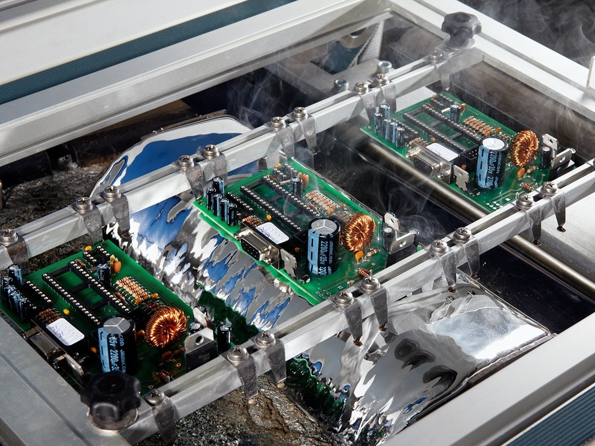
Mass selective dip solder fountain systems involve dipping a PCB into a fountain of molten solder through customized tooling. The tooling features apertures that align with the areas to be soldered, allowing solder to flow only to designated spots. The board is lowered onto the fountain, and all targeted points are soldered simultaneously, making this method faster than point-to-point techniques.
The principle behind this system is based on controlled solder flow. Pumps maintain a consistent fountain of solder, and the tooling ensures precision by masking off areas that must remain unsoldered. This approach is efficient for through-hole components and can handle multiple joints at once, improving throughput in production settings.
One limitation is the need for custom tooling for each PCB design, which can increase lead times and costs for low-volume runs. Additionally, maintaining uniform solder flow and temperature is critical to avoid defects like bridging or insufficient wetting, as defined by IPC-6012E for rigid board performance specifications.
Selective Aperture Tooling Over Wave Solder
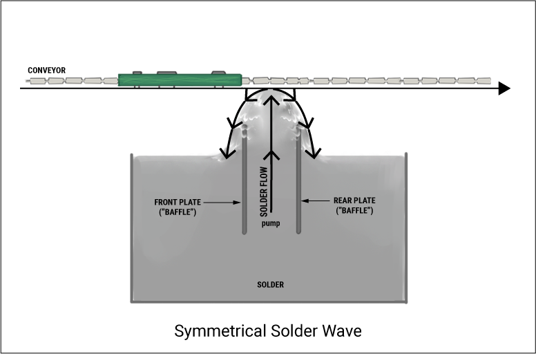
Selective aperture tooling over wave solder adapts the traditional wave soldering process by using specialized masks or pallets with openings that expose only the areas to be soldered. The PCB passes over a wave of molten solder, but the tooling restricts contact to specific points, protecting other regions from solder exposure. This method combines the speed of wave soldering with a degree of selectivity.
The mechanism relies on a conveyor system moving the PCB over a solder wave while the tooling acts as a barrier. The apertures in the tooling align with through-hole leads or pads requiring solder, ensuring controlled application. This technique is often used for mixed assemblies where some through-hole components need soldering after surface-mount reflow.
While this method is cost-effective for medium to high-volume production, it lacks the precision of other selective systems. There is a risk of solder bridging or uneven application if the tooling is not perfectly aligned. Compliance with standards like J-STD-020E for moisture and reflow sensitivity is essential to ensure component safety during the process.
Practical Applications and Best Practices
Choosing the Right System for Your Needs
Selecting the appropriate selective soldering system depends on several factors, including PCB design complexity, production volume, and component sensitivity. Laser selective soldering systems are best suited for high-precision tasks involving fine-pitch or heat-sensitive components. Electrical engineers working on advanced telecommunications or medical devices often prefer this method for its pinpoint accuracy, despite slower processing speeds.
Mass selective dip solder fountains excel in scenarios requiring higher throughput for through-hole components. This system is practical for automotive or industrial electronics where multiple joints need simultaneous soldering. Engineers must ensure that custom tooling is designed with precision to avoid misalignment and defects, adhering to guidelines in IPC-6012E for performance specifications.
Selective aperture tooling over wave solder offers a balance between cost and selectivity, making it suitable for medium-volume production of consumer electronics. It is less precise than other methods, so engineers should verify tooling accuracy and monitor for potential solder defects as per IPC-A-600K acceptability criteria.
Best Practices for Implementation
To optimize selective soldering outcomes, engineers should focus on process control and equipment maintenance. For laser systems, regular calibration of laser intensity and focus is necessary to maintain joint quality. Monitoring thermal profiles ensures compliance with component specifications under J-STD-020E.
In mass selective dip solder fountains, maintaining consistent solder temperature and flow prevents defects like cold joints. Periodic inspection of tooling for wear or misalignment helps sustain precision. Engineers should also use flux compatible with the solder alloy to enhance wetting, following industry-accepted practices.
For selective aperture tooling over wave solder, ensuring proper alignment between the PCB and tooling is critical. Preheating the board can reduce thermal shock, and post-soldering inspection should check for bridging or insufficient solder, aligning with IPC-A-600K standards for visual acceptability.
Troubleshooting Common Issues
Selective soldering systems, while effective, can encounter issues that impact assembly quality. In laser soldering, overheating can damage components if laser parameters are not optimized. Engineers should adjust energy levels based on material properties and verify settings against component tolerances.
Mass selective dip solder fountains may produce solder bridging if tooling apertures are too large or misaligned. Adjusting the design and conducting trial runs can identify potential flaws before full production. Insufficient solder wetting can also occur if flux application is uneven, requiring process optimization.
With selective aperture tooling over wave solder, uneven solder waves can lead to incomplete joints. Regular maintenance of the wave system and precise tooling fabrication are essential to mitigate this. Visual inspection post-soldering, guided by IPC-A-600K, helps detect and address such defects promptly.
Conclusion
Selective soldering systems offer tailored solutions for modern PCB assembly challenges, enabling electrical engineers to achieve precision and reliability in mixed-technology boards. Laser selective soldering systems provide unmatched accuracy for intricate designs, while mass selective dip solder fountains prioritize efficiency for through-hole applications. Selective aperture tooling over wave solder balances cost and selectivity for broader production needs. Understanding the technical principles and best practices of each system empowers engineers to select the most suitable method for their projects. By adhering to recognized industry standards and focusing on process control, high-quality outcomes are achievable across diverse applications.
Related Reading: Common PCB Soldering Defects: Causes, Impacts, and Prevention for Reliable Assemblies
FAQs
Q1: How does a laser selective soldering system ensure precision in PCB assembly?
A1: A laser selective soldering system uses a focused beam to heat specific solder joints without affecting nearby areas. This pinpoint accuracy is ideal for fine-pitch components on densely populated boards. By controlling laser intensity and duration, engineers prevent thermal damage, ensuring reliable connections. This method aligns with strict quality standards for acceptability in electronics assembly.
Q2: What are the main advantages of a mass selective dip solder fountain for through-hole components?
A2: A mass selective dip solder fountain solders multiple through-hole joints simultaneously, boosting production efficiency. Custom tooling with apertures directs solder only to targeted areas, reducing thermal stress on other components. This method suits high-throughput environments like automotive electronics. Proper tooling design and maintenance are key to avoiding defects and maintaining consistent quality.
Q3: Why choose selective aperture tooling over wave solder for mixed assemblies?
A3: Selective aperture tooling over wave solder combines the speed of wave soldering with controlled solder application via custom masks. It protects sensitive areas from solder exposure, making it suitable for mixed assemblies. This approach is cost-effective for medium-volume runs, though precision is lower compared to other systems. Alignment and inspection ensure defect-free results.
Q4: What standards guide the quality of selective soldering processes?
A4: Standards like IPC-A-600K for PCB acceptability and IPC-6012E for performance specifications are critical in selective soldering. J-STD-020E also provides guidelines on moisture and reflow sensitivity to protect components. Adhering to these ensures consistent quality, minimizes defects, and supports reliability in various selective soldering systems for electrical engineers.
References
IPC-A-600K — Acceptability of Printed Boards. IPC, 2020.
IPC-6012E — Qualification and Performance Specification for Rigid Printed Boards. IPC, 2020.
JEDEC J-STD-020E — Moisture/Reflow Sensitivity Classification. JEDEC, 2014.


