Introduction
Buzzers serve as critical audible indicators in electronic devices, from consumer gadgets to industrial controls, alerting users to events or statuses. Ensuring buzzer reliability is essential for preventing buzzer failure, which can lead to system downtime or safety issues in applications like alarms and notifications. Engineers often face challenges with buzzers due to their mechanical nature, making them susceptible to wear over time. This article provides practical tips on buzzer operating conditions, environmental effects on buzzers, and strategies for extending component lifespan. By focusing on design, assembly, and maintenance best practices, you can significantly enhance buzzer performance and longevity. These insights draw from established engineering principles to help electric engineers optimize their PCB designs.
Understanding Buzzer Types and Their Reliability Factors
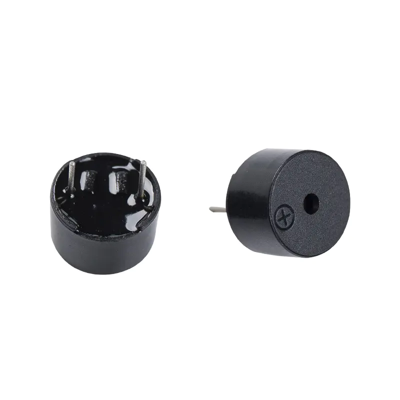
Buzzers primarily fall into two categories: piezoelectric and electromagnetic, each with distinct operating mechanisms that influence their reliability. Piezoelectric buzzers use a ceramic disc that vibrates when voltage is applied, producing sound through resonance with a metal diaphragm. Electromagnetic buzzers rely on a coil and magnet to drive a vibrating armature, generating tone via mechanical oscillation. Piezoelectric types offer higher sound pressure levels at lower currents but require precise voltage matching to avoid overdriving. Electromagnetic variants handle lower voltages better but draw more current and are prone to coil degradation. Selecting the right type based on application demands is the first step in preventing buzzer failure.
Reliability differences stem from material sensitivities. Piezo elements can crack under excessive drive signals, while electromagnetic armatures fatigue from repeated cycles. Both types benefit from derating voltage by 10 to 20 percent below rated values to extend component lifespan. Engineers should review datasheet specifications for rated voltage, current, and frequency ranges during selection. Matching drive circuits to these parameters prevents early degradation. Adhering to component footprints as per IPC-7351 standards ensures proper mechanical stress distribution during assembly.
Common Causes of Buzzer Failure in Electronic Assemblies
Overvoltage stands out as a primary cause of buzzer failure, leading to immediate damage like cracking in piezoelectric discs or burning coils in electromagnetic models. Exceeding rated voltage generates excessive mechanical stress, fracturing delicate structures within cycles. Current surges from poor power supply regulation exacerbate this, causing thermal runaway in drive circuits. Mechanical fatigue from continuous operation ranks second, where vibration wears solder joints or diaphragms over time. Poor soldering, such as insufficient fillet or voids, accelerates joint failure under thermal cycling.
Connection issues, including loose wires or PCB trace cracks, interrupt signals and mimic total failure. Contamination from flux residues promotes corrosion, especially in humid environments. Overdriving with mismatched frequencies detunes resonance, reducing output and stressing components. Troubleshooting starts with multimeter checks on voltage and continuity, followed by oscilloscope analysis of drive signals. Visual inspection reveals physical cracks or discoloration indicative of abuse. Addressing these root causes through proactive design minimizes field returns.

Optimizing Buzzer Operating Conditions for Longevity
Buzzer operating conditions directly dictate lifespan, with voltage stability being paramount. Piezoelectric buzzers typically require higher voltages, around 12 to 220 volts at low currents under 20 milliamps, while electromagnetic ones operate at 1.5 to 12 volts with higher currents. Always incorporate voltage regulators or zener diodes to clamp spikes, preventing excursions beyond tolerances. Frequency matching to the buzzer's resonant point maximizes efficiency and reduces drive power, thereby cutting heat generation.
Duty cycle management extends component lifespan by limiting continuous operation. Intermittent use, such as pulsed tones, allows cooling and reduces fatigue. Thermal considerations are crucial, as elevated temperatures accelerate material aging in both types. Position buzzers away from high-heat sources like power ICs on the PCB. Monitor junction temperatures during prototyping to stay within specified ranges, often -40 to 85 degrees Celsius. Drive circuits with feedback loops adjust signals dynamically, enhancing buzzer reliability under varying loads.
Mitigating Environmental Effects on Buzzers
Environmental effects on buzzers pose significant risks, particularly humidity and vibration in real-world deployments. High humidity penetrates seals, causing electrochemical migration that shorts internal contacts or corrodes coils. Conformal coatings applied post-assembly protect against moisture ingress without damping acoustics. Temperature extremes depolarize piezo ceramics or demagnetize electromagnetic cores, shifting performance. Select buzzers rated for the full operational range, and use potting compounds for harsh environments.
Vibration from machinery or user handling fatigues solder joints and diaphragms. Secure mounting with epoxy or mechanical clips absorbs shocks. Dust accumulation clogs ports, muffling sound and promoting internal wear. IP-rated enclosures shield against particulates. Cyclic exposure to thermal gradients induces stress cracks via coefficient of thermal expansion mismatches between buzzer and PCB. Compliance with IPC-A-610 criteria during assembly ensures robust joints resistant to these effects. Regular environmental stress screening during qualification catches weak points early.

Best Practices in PCB Design and Assembly for Buzzer Reliability
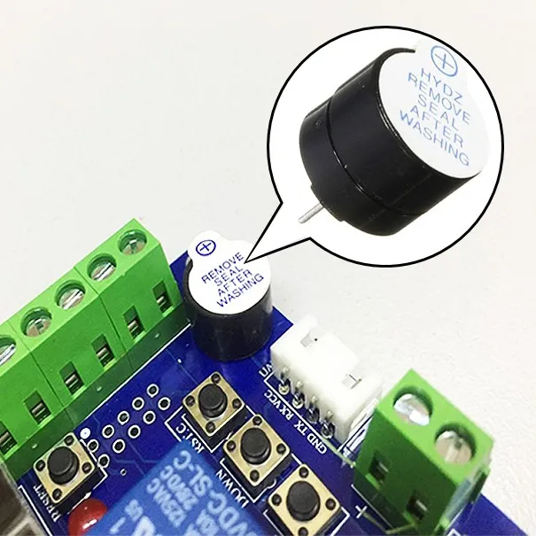
PCB layout plays a key role in preventing buzzer failure through strategic placement and routing. Position buzzers on board edges for unobstructed sound propagation and easy access during testing. Wide traces for power delivery minimize voltage drops, ensuring stable drive. Ground planes reduce noise coupling into signal lines. Land pattern design per IPC-7351 prevents tombstoning or bridging in SMT processes.
Assembly processes demand precision to enhance buzzer reliability. Reflow soldering profiles must respect JEDEC J-STD-020 moisture sensitivity levels, baking components pre-assembly if needed. Avoid hand soldering near buzzers to prevent thermal shock. Post-reflow cleaning removes residues that could lead to dendrite growth. Conformal coating thickness should uniform, typically 25 to 75 microns, to avoid acoustic interference. Functional testing post-assembly verifies output levels and frequency response under load.
Vibration damping materials under the buzzer footprint absorb operational resonances. Firmware limits drive duration and amplitude, providing software-level protection. These combined hardware and software safeguards extend component lifespan substantially.
Testing Strategies to Verify Buzzer Lifespan and Performance
Accelerated life testing simulates years of use in hours, applying elevated voltage or temperature while monitoring sound output decay. Vibration tables per IEC 60068 replicate field stresses, checking joint integrity. Sound level meters quantify pressure levels over cycles, detecting early degradation. Thermal cycling chambers expose assemblies to -40 to 125 degrees Celsius ramps, inspecting for cracks via X-ray or dye penetrant.
In-circuit tests during production scan for open circuits or shorts. Burn-in screens at elevated conditions weed out infant mortalities. Field data logging tracks real-world performance, informing design iterations. These methods ensure buzzers meet reliability targets before deployment.
Conclusion
Extending component lifespan requires a holistic approach encompassing proper selection, design, assembly, and testing tailored to buzzer operating conditions. By addressing common failure modes like overvoltage, mechanical fatigue, and environmental effects on buzzers, engineers can achieve superior buzzer reliability. Adhering to standards such as IPC-A-610 and JEDEC J-STD-020 during processes fortifies assemblies against real-world stresses. Implementing these tips minimizes failures, reduces warranty costs, and boosts product reputation. Electric engineers equipped with this knowledge can deliver robust, long-lasting designs.
FAQs
Q1: How can engineers improve buzzer reliability in high-vibration environments?
A1: Mount buzzers with damping pads or epoxy to isolate vibrations from solder joints. Use conformal coatings to protect against fatigue-induced cracks. Select models rated for the expected G-forces, and test assemblies on shaker tables. Drive signals intermittently to reduce self-generated resonances. These steps prevent buzzer failure effectively.
Q2: What are optimal buzzer operating conditions to avoid premature wear?
A2: Maintain voltage 10 to 20 percent below rated values using regulators. Limit duty cycles to under 50 percent for continuous tones. Keep temperatures within -40 to 85 degrees Celsius, avoiding hot zones. Match drive frequency to resonance for efficiency. This extends component lifespan significantly.
Q3: How do environmental effects on buzzers impact performance?
A3: Humidity causes migration and corrosion, while high temperatures age materials. Vibration loosens joints over time. Protect with IP seals, coatings, and robust mounting. Qualify via environmental chambers. Proper mitigation preserves buzzer reliability.
Q4: What PCB assembly practices enhance preventing buzzer failure?
A4: Follow IPC-A-610 for solder joint criteria. Bake MSL components per JEDEC J-STD-020 before reflow. Apply uniform conformal coating. Test post-assembly for output. These ensure long-term integrity.
References
IPC-A-610H — Acceptability of Electronic Assemblies. IPC
IPC-7351D — Generic Requirements for Surface Mount Design and Land Pattern Standard. IPC
JEDEC J-STD-020E — Moisture/Reflow Sensitivity Classification of Nonhermetic Surface Mount Devices. JEDEC