Introduction
Solder mask is far more than a cosmetic green coating. It serves as the primary insulation layer between copper features, protects against oxidation, prevents solder bridges, and directly influences PCBA assembly yield and long-term reliability. Different applications (high-temperature, high-voltage, flex, RF, LED, automotive) demand specific solder mask properties. This practical selection guide helps engineers and procurement teams choose the optimal type from the first design review.
Major Solder Mask Types and Their Properties
| Type | Typical Tg | CTE (ppm/°C) | Dielectric Strength | Key Advantages | Typical Applications |
|---|---|---|---|---|---|
| Standard LPI (Liquid Photoimageable) | 100–120 °C | 60–80 | 500–800 V/mil | Cost-effective, good resolution | Consumer, industrial |
| High-Tg LPI | 140–170 °C | 40–55 | 700–1000 V/mil | Lead-free reflow, automotive under-hood | Automotive, power supplies |
| Low-CTE / High-Thermal | 160–190 °C | 15–30 | 800–1200 V/mil | Multiple reflow cycles, large BGAs | Servers, telecom, LED COB |
| Flexible / Polyimide-based | 20–80 °C | 30–60 | 1000+ V/mil | Bend radius < 5 mm, dynamic flex | Wearables, medical devices, flex-rigid |
| High-Voltage / Thick-film | 130–150 °C | 50–70 | > 2000 V/mil | 20–50 µm thickness, creepage distance | EV chargers, industrial motor drives |
| Low-Dk / RF-specific | 120–160 °C | 40–60 | 600–900 V/mil | Dk 3.0–3.5, low loss tangent | 5G mmWave, radar, high-speed SerDes |
| Matte Black (for AOI) | 110–150 °C | 50–70 | 600–900 V/mil | High contrast for automated inspection | High-reliability aerospace, medical |
Selection Guide by Application
High-Temperature Environments
- Multiple lead-free reflow + wave soldering
- Automotive under-hood (125–150 °C continuous)
- → Choose high-Tg (≥ 150 °C) or low-CTE LPI
- LED COB, SiP with molding → Low-CTE, high-reflection white mask
Flexible and Flex-Rigid PCBs
- Dynamic or installation bending
- → Use dedicated flexible polyimide or flexible LPI (20–50 µm final thickness)
- Never use standard rigid LPI on flex zones (will crack)
High-Voltage Designs (> 500 V)
- Creepage and clearance distances critical
- → Specify high-voltage thick-film mask (30–50 µm) or double-pass LPI
- Add rounded mask openings and large mask dams between HV pads
RF and High-Speed Digital
- 5G, mmWave, 112 Gbps PAM4
- → Low-Dk, low-loss tangent mask (Dk < 3.5 @ 10 GHz)
- Avoid mask over ground pour in CPW or microstrip areas when possible
Harsh Chemical or Cleaning Environments
- No-clean flux residue + aggressive washing
- → Select high-adhesion, chemical-resistant formulations (often matte black or dark colors)
Suggested Reading: What is a Solder Mask Bridge in PCB Design?
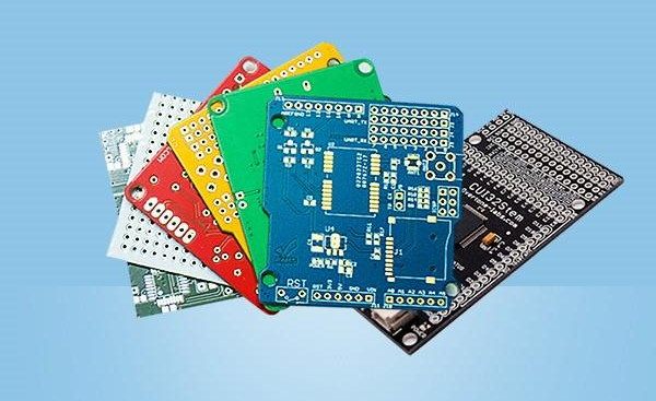
Color Selection – It’s Not Just Cosmetic
| Color | Practical Benefit |
|---|---|
| Green (gloss/matte) | Industry standard, good contrast for manual inspection |
| Matte Black | Best AOI/AXI contrast, hides competitor reverse-engineering |
| White | Highest light reflectivity for LED boards (> 90 %) |
| Blue / Red | Visual identification of different revisions |
| Clear | Allows copper visibility for RF tuning |
Compatibility with Assembly Process
| Process | Recommended Mask Type |
|---|---|
| Multiple lead-free reflow | High-Tg ≥ 150 °C |
| Wave soldering (through-hole) | Standard or high-Tg LPI |
| Selective soldering | High-temperature resistance |
| Conformal coating | Good adhesion primer (most modern LPIs) |
| ENIG / Immersion silver | Standard LPI (avoid overly aggressive photoinitiators) |
Specification Tips for Fabrication Drawing
- Call out exact mask type (e.g., “High-Tg LPI, Taiyo PSR-4000 AUS5 or equivalent”)
- State minimum mask thickness over traces (25 µm typical)
- Specify matte or gloss finish
- Define mask clearance (0.05–0.10 mm typical) and web thickness
- For flex: “Flexible LPI, 20–30 µm final thickness in bend areas”
Conclusion
Choosing the correct solder mask is a reliability decision, not just cosmetic. Standard green LPI works perfectly for most consumer products, but high-temperature, high-voltage, flexible, or RF designs demand specialized formulations. Always verify the mask datasheet for Tg, CTE, dielectric strength, and flammability (UL 94V-0) before final selection.
FAQs
QX: Can I use standard green solder mask on flexible PCBs?
AX: No. Standard rigid LPI cracks within a few bend cycles. Use dedicated flexible or polyimide-based mask.
QX: Is matte black solder mask more expensive?
AX: Only 5–10 % higher than standard green for most fabricators. The AOI yield improvement often justifies the cost.
QX: Do I need special solder mask for 300 °C reflow?
AX: Yes. For extreme processes (e.g., die-attach sintering), select masks rated ≥ 170 °C Tg with low CTE.
QX: Will white solder mask affect LED brightness?
AX: Yes, positively. High-reflectivity white mask can increase lumen output 10–25 % versus green in COB applications.
References
IPC-SM-840E — Qualification and Performance Specification of Permanent Solder Mask. IPC, 2010.
IPC-6012E — Qualification and Performance Specification for Rigid Printed Boards. IPC, 2017.
IPC-A-600K — Acceptability of Printed Boards. IPC, 2020.
IPC-J-STD-004B — Requirements for Soldering Fluxes. IPC, 2008.


