Introduction
Ensuring the reliability of printed circuit board (PCB) assemblies is a critical task in electronics manufacturing. As an assembly engineer, I understand the immense value of robust testing methodologies. Among these, the In Circuit Test (ICT) stands out as a highly effective approach, primarily through its use of specialized ICT Test Fixtures for comprehensive component-level verification. This guide delves into how these fixtures facilitate precise testing, detect common defects, and ultimately contribute to high-quality PCB assembly.
What is Component-Level Testing and Why It Matters for PCB Assembly
Component-level testing refers to the process of electrically verifying individual components on a populated PCB assembly. Instead of merely checking the overall functionality of the entire circuit, component-level testing scrutinizes each passive and active component to confirm its presence, correct value, and proper orientation. This granular approach is fundamental to quality assurance in PCB assembly.
The importance of component-level testing for PCB assembly cannot be overstated. Defects introduced during the assembly process, such as incorrect component placement, faulty solder joints, or the use of wrong parts, can significantly impair a board's performance or cause outright failure. Catching these issues at the component level early in the production cycle is far more cost-effective than discovering them during later stages, such as functional testing or after product shipment. Early detection minimizes rework, reduces scrap rates, and prevents costly field failures, directly impacting manufacturing efficiency and product reliability. An effective ICT test for PCB assembly provides this critical early feedback.
Technical Principles: How ICT Fixtures Enable Component-Level Testing
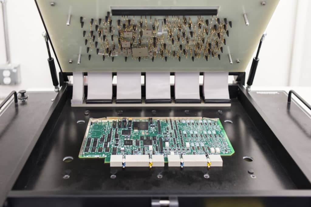
The heart of component-level testing using ICT lies in the design and operation of the ICT Test Fixture. This fixture is a custom-engineered interface that provides dedicated access to the individual nodes and component leads on a PCB assembly.
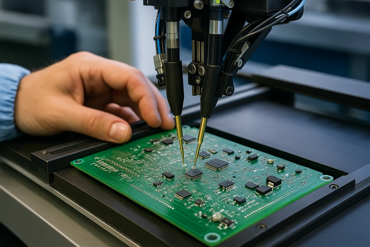
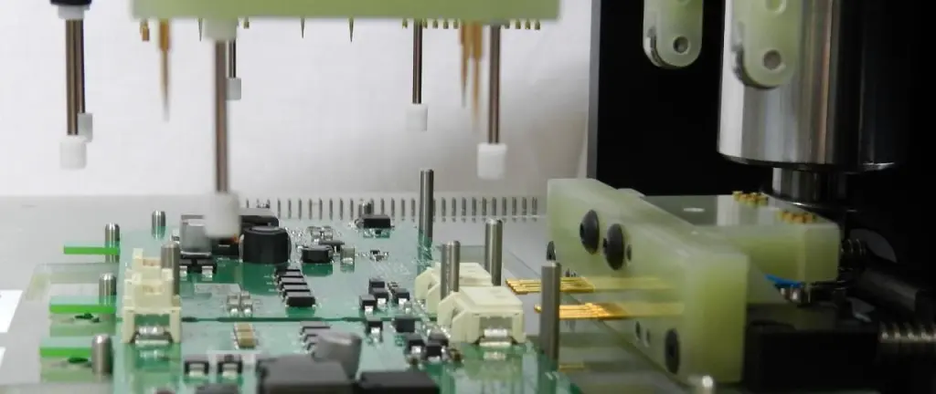
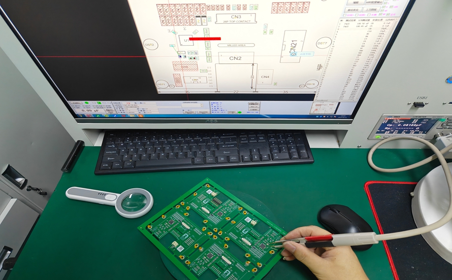
An ICT Test Fixture typically consists of a "bed of nails" – an array of spring-loaded pins, also known as pogo pins. These pins are precisely machined and positioned to align with specific test points, component pads, or vias on the PCB under test. When the PCB assembly is loaded into the fixture, it is pressed down, causing the pogo pins to make reliable physical contact with the designated test points. This physical connection allows the ICT system to isolate individual components or small sections of the circuit for measurement.
The ICT machine, connected to the fixture, then applies controlled electrical signals and measures the responses. This isolation capability is key to component-level testing. By energizing specific nodes and grounding others, the system can effectively "look at" each component independently, verifying its characteristics without interference from adjacent circuitry. The design of the PCB assembly must incorporate sufficient and accessible test points to enable this comprehensive component-level testing, a practice known as Design for Testability (DfT). IPC-2221B, "Generic Standard on Printed Board Design," offers guidance on implementing such test features.
Key Verification Tests: Shorts and Opens Testing
Among the most fundamental checks performed by an ICT test for PCB assembly are shorts and opens testing. These are critical for detecting basic connectivity defects that can cripple a board.
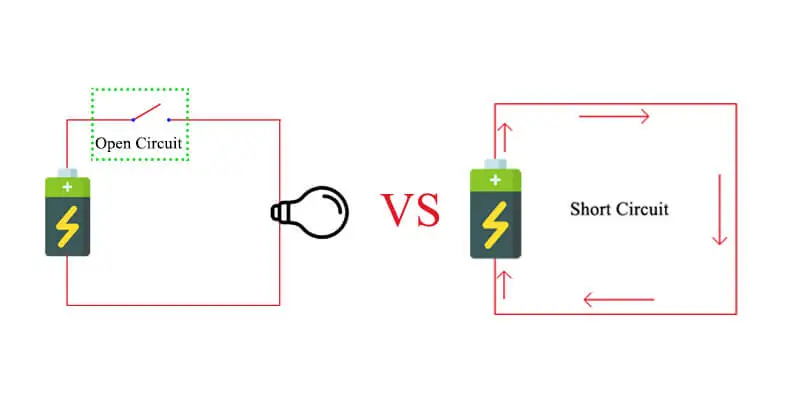
Shorts testing aims to identify unintended low-resistance paths between two points that should be electrically isolated. These can occur due to solder bridges between adjacent traces, pads, or component leads, or even debris trapped under components. The ICT system performs this by applying a small voltage between all combinations of test points and measuring the resistance. If the resistance falls below a predefined threshold, indicating an unintended connection, a short is detected. This test is extremely fast and effective at catching common manufacturing defects that arise during solder paste application or reflow soldering.
Opens testing, conversely, identifies unintended breaks in an electrical path. This could be a result of a missing component, a poor or incomplete solder joint, a broken trace on the PCB, or a component lead that is not making proper contact with its pad. For opens testing, the ICT system injects a current or voltage and measures for continuity. An infinitely high resistance or a lack of expected voltage drop indicates an open circuit. By systematically checking connections across every component and trace, the ICT test for PCB assembly ensures that all intended electrical paths are complete and robust. Both shorts and opens testing are foundational for verifying the basic structural integrity of the assembled board.
Key Verification Tests: Resistance and Capacitance Measurement
Beyond basic connectivity, ICT Test Fixtures enable precise electrical characterization through resistance measurement and capacitance measurement. These checks confirm that components are not only present but also have the correct electrical values.
Resistance measurement involves applying a known current across a resistor or a resistive path and measuring the resulting voltage drop. Using Ohm's Law, the system calculates the resistance and compares it against the expected value specified in the Bill of Materials (BOM) and its acceptable tolerance range. If the measured resistance deviates significantly, it indicates an incorrect resistor, a faulty resistor, or a solder issue affecting the component's value. This is a primary method for ensuring the correct component-level testing of resistors.
Capacitance measurement follows a similar principle, though it often involves applying an AC signal to a capacitor and measuring its impedance. The system calculates the capacitance and verifies it against the specified value and tolerance. Incorrect capacitance can lead to timing issues, signal integrity problems, or power delivery faults in a circuit. Accurate capacitance measurement is vital for components like decoupling capacitors, timing circuits, and filters. By performing both resistance measurement and capacitance measurement, the ICT system provides a high degree of confidence that the passive components on the board assembly are correct and functioning as intended.
Beyond Basic Measurements: Other Component-Level Checks
While shorts and opens testing, along with resistance measurement and capacitance measurement, form the core of ICT, modern systems can perform more sophisticated component-level checks.
- Inductance Measurement: Similar to capacitance, inductors can be measured using AC signals to verify their specified inductance values, crucial for power supplies and RF circuits.
- Diode and Transistor Testing: ICT can verify the forward voltage drop of diodes and the basic functionality (e.g., gain for transistors) of active semiconductor devices. It checks for correct orientation (polarity) and absence of opens or shorts across their junctions.
- Simple Analog and Digital IC Checks: For some integrated circuits, ICT can perform "truth table" testing or functional subset testing. This involves applying specific input patterns to the IC's pins and verifying the expected output responses. While not a full functional test, it confirms the IC's presence, correct orientation, and basic operational integrity at the component level.
- Presence Detection: For certain components, the ICT system might simply verify the electrical signature of a component to confirm its presence, even if a full characterization is not performed or necessary.
These expanded capabilities allow for a very high level of component-level testing, catching a broader array of defects that might otherwise escape detection until more expensive functional testing or even field failures. Adherence to standards like J-STD-001G, "Requirements for Soldered Electrical and Electronic Assemblies," ensures that soldering processes support the intended electrical characteristics for these components.
Practical Considerations: Design for Testability (DfT) and Fixture Maintenance
To maximize the effectiveness of ICT Test Fixtures for component-level verification, two practical considerations are paramount: Design for Testability (DfT) and diligent fixture maintenance.
DfT is the practice of designing a PCB with testing in mind from the outset. This involves ensuring adequate access to test points for every component and critical node. Without well-planned test points, the ICT Test Fixture cannot make the necessary physical contacts for comprehensive shorts and opens testing, resistance measurement, or capacitance measurement. Designers should consider guidelines such as those found in IPC-2221B to optimize board layouts for testability, balancing component density with test access. Early DfT implementation can significantly reduce testing costs and improve test coverage.
Fixture maintenance is equally crucial. The longevity and accuracy of an ICT Test Fixture depend on regular care. Over time, the spring-loaded pins can wear out, bend, or accumulate debris, leading to unreliable physical contacts. Poor contact can result in false failures, where a perfectly good board is incorrectly flagged as defective, or missed defects. Regular cleaning of the pogo pins, inspection for wear and damage, and timely replacement of faulty pins are essential to maintain the fixture's integrity and ensure consistent, accurate component-level testing results. Proper maintenance is a key aspect of ensuring overall quality management, aligning with principles in ISO 9001:2015, "Quality Management Systems."
Conclusion
ICT Test Fixtures are indispensable tools for achieving high-quality PCB assembly through meticulous component-level verification. By providing precise physical contacts, these fixtures enable comprehensive shorts and opens testing, accurate resistance measurement, and reliable capacitance measurement. They allow assembly engineers to systematically identify and diagnose manufacturing defects at the earliest possible stage. Integrating robust Design for Testability practices and adhering to a strict fixture maintenance schedule are vital to harnessing the full potential of ICT. This commitment to detailed component-level testing ensures that board assemblies meet stringent quality standards, contributing to the overall reliability and performance of electronic products.
FAQs
Q1: What is the main purpose of an ICT test for PCB assembly?
A1: The main purpose of an ICT test for PCB assembly is to perform component-level testing, verifying the integrity and correct placement of individual components on a populated circuit board. It detects manufacturing defects like shorts, opens, incorrect parts, and misorientations by taking precise electrical measurements using a specialized fixture.
Q2: How do ICT Test Fixtures perform component-level testing?
A2: ICT Test Fixtures use an array of spring-loaded pins (pogo pins) to establish physical contacts with test points on the PCB assembly. This allows the ICT system to isolate individual components or circuit paths to perform specific tests, such as resistance measurement and capacitance measurement, ensuring each component meets its electrical specifications.
Q3: What are shorts and opens testing in the context of ICT?
A3: Shorts and opens testing are fundamental component-level tests performed by ICT. Shorts testing identifies unintended electrical connections (e.g., solder bridges) between isolated points, while opens testing detects breaks in intended electrical paths (e.g., poor solder joints, missing components). Both are crucial for verifying the basic connectivity of a PCB assembly.
Q4: Why is resistance measurement and capacitance measurement important in ICT?
A4: Resistance measurement and capacitance measurement are important in ICT for verifying the correct values of passive components. These tests ensure that resistors have the specified resistance and capacitors have the correct capacitance, confirming that the right components are placed correctly and are not faulty, which is vital for the proper functioning of the PCB assembly.
References
IPC-A-610G — Acceptability of Electronic Assemblies. IPC, 2017.
IPC-2221B — Generic Standard on Printed Board Design. IPC, 2012.
J-STD-001G — Requirements for Soldered Electrical and Electronic Assemblies. IPC/JEDEC, 2017.
ISO 9001:2015 — Quality Management Systems. ISO, 2015.