Introduction
In the realm of Printed Circuit Board (PCB) assembly, thorough testing is essential to guarantee product reliability and functionality. As an assembly engineer, I have witnessed the evolution of testing methodologies firsthand. The fundamental choice often lies between traditional manual inspection and the advanced capabilities of automated systems like In Circuit Test (ICT) using specialized fixtures. This article will make a clear case for automation, highlighting its critical benefits over manual approaches in ensuring high-quality board assemblies.
What Are ICT Test Fixtures and How Do They Work?
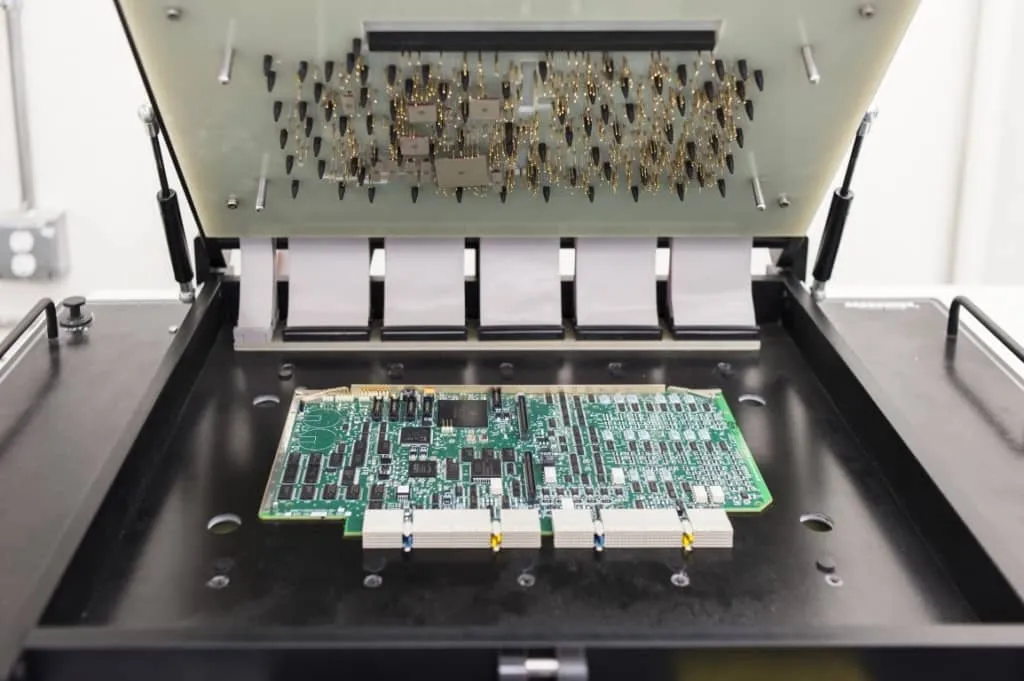
ICT test fixtures act as a custom mechanical and electrical interface between the PCB assembly and automated test equipment. The core design is a “bed-of-nails” array: hundreds or thousands of spring-loaded pogo pins are precisely positioned to align with dedicated test points or component pads on the board.
During testing, the PCB is placed and secured in the fixture (via vacuum, pneumatic pressure, or mechanical means). The probes make simultaneous, reliable physical contacts. The automated system then applies controlled voltages and currents through these contacts while measuring responses such as resistance, capacitance, inductance, continuity, and logic states. Software on the automation computer compares results against programmed tolerances and generates pass/fail diagnostics with exact fault locations.
This parallel approach enables comprehensive testing in seconds rather than sequential manual probing. Fixtures are tailored to specific PCB layouts, incorporating alignment features and requiring regular maintenance (cleaning and probe replacement) to avoid false failures or escapes. Overall, ICT test fixtures transform testing from labor-dependent manual checks into fast, automated, component-level verification.
The Challenges of Manual PCB Testing
Before the widespread adoption of automated equipment, manual testing was the primary method for verifying PCB assembly quality. This often involved visual inspection by skilled technicians using microscopes, and continuity checks with multimeters. While experienced human eyes can identify many obvious defects, this approach presents significant challenges.
Manual testing is inherently slow and labor intensive. Each board assembly requires individual attention, leading to bottlenecks in production lines. Furthermore, human inspection is prone to error. Fatigue, distraction, or subtle variations in components can lead to missed defects. The consistency of results can vary greatly from one inspector to another, making it difficult to maintain uniform quality standards. Subjectivity in defect identification can result in unnecessary rework or, worse, the shipment of faulty products. Such inconsistencies directly impact manufacturing efficiency and increase overall costs due in part to higher scrap rates and warranty claims. In contrast, automated solutions rely on proven bed-of-nails technology for consistent results.
Introducing ICT Test Fixtures and Automated Equipment
The advent of ICT Test Fixtures marked a significant leap forward in PCB assembly testing. This method moves away from manual processes towards a highly efficient, automated approach. An ICT Test Fixture is a custom engineered interface that provides precise physical contacts to specific test points on a board assembly. These fixtures are integrated with sophisticated automated equipment, forming a complete testing system. For a full breakdown of component-level verification using these fixtures, see our ICT Test Fixtures for PCB Testing: A Component-Level Verification Guide.
The automated equipment, controlled by an automation computer, systematically performs electrical measurements and logic measurements across the entire board. This automation eliminates the human variability inherent in manual testing. It ensures that every board assembly undergoes the same rigorous set of checks, providing consistent and repeatable results. The core strength of ICT lies in its ability to isolate and identify individual component failures or manufacturing defects at high speed and with exceptional accuracy.
Technical Advantages of Automation: Electrical and Logic Measurements
Automated equipment, specifically ICT systems, offers profound technical advantages through its precise electrical measurements and logic measurements. These capabilities are far beyond what manual methods can consistently achieve.
The system uses its array of physical contacts to apply controlled currents and voltages to individual nodes on the PCB. It then measures the resulting electrical parameters, such as resistance, capacitance, and inductance, across components. For instance, the automated equipment can verify if a resistor’s value falls within its specified tolerance or if a capacitor exhibits the correct capacitance. These electrical measurements are critical for confirming the correct placement and functionality of passive components.
Beyond passive components, modern ICT systems are also capable of performing logic measurements. This involves verifying the correct operation of digital integrated circuits (ICs). By applying specific input patterns to an IC's pins via the physical contacts and monitoring the output responses, the automation computer can determine if the IC is functioning as designed. This is crucial for detecting misoriented or faulty digital components. The speed at which these measurements are taken, often thousands per second, allows for comprehensive testing of complex board assemblies in a matter of seconds.
The precision and repeatability of these measurements, driven by the automation computer, ensure that even subtle deviations from expected values are detected. This detailed diagnostic capability provides valuable feedback for process control and quality improvement in the manufacturing line.
Measurement Examples Table:
| Parameter | What It Tests | Key Benefit vs. Manual Testing |
|---|---|---|
| Resistance | Component value & tolerance | Instant detection of wrong or out-of-spec parts |
| Capacitance/Inductance | Passive component correctness | Identifies damaged or missing elements quickly |
| Shorts/Opens | Solder joint integrity | Precise fault location for fast rework |
| Logic/Function | Digital IC operation & orientation | Verifies complex active components reliably |
The Role of Physical Contacts in Automated Testing
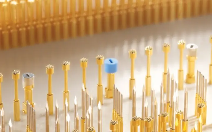
The success of ICT Test Fixtures and automated testing hinges on the integrity and accuracy of their physical contacts. These contacts are typically spring-loaded probes, often called pogo pins, meticulously arranged within the fixture. Each pogo pin is precisely positioned to connect with a specific test point or pad on the board assembly.
The reliability of these physical contacts is paramount. A well designed fixture ensures that every pin makes solid and consistent contact with its target. This is achieved through careful mechanical design and alignment of the fixture to the PCB. Poor contact can lead to "false failures," where a defect is reported when none exists, or, conversely, "escapes," where a real defect goes undetected. To prevent this, fixtures require regular maintenance, including cleaning and replacement of worn or bent probes.
The ability to establish multiple, simultaneous physical contacts across the entire board assembly is what gives ICT its comprehensive testing power. Instead of checking one point at a time manually, the automated equipment can access hundreds or even thousands of test points concurrently. This parallel testing capability dramatically reduces test time while increasing the depth of fault detection. Adherence to industry guidelines for test point accessibility, as detailed in standards like IPC-2221B, "Generic Standard on Printed Board Design," is essential during the PCB design phase to enable effective physical contact by the fixture.
Related Reading: What You Need to Know Before Designing an ICT Test Fixture
Making the Case for Automation: Efficiency, Accuracy, and Cost Savings
The transition from manual testing to automated equipment, especially ICT Test Fixtures, represents a compelling case for automation in PCB assembly. The benefits span across efficiency, accuracy, and significant cost savings.
Enhanced Efficiency
Automated systems can test board assemblies in seconds, a stark contrast to the minutes or even hours required for thorough manual inspection. This drastically increases throughput, allowing manufacturing lines to handle higher volumes without additional labor. The automation computer rapidly processes electrical measurements and logic measurements, generating instant pass or fail reports.
Unparalleled Accuracy and Repeatability
The precision of automated equipment virtually eliminates human error. Every test is performed identically, ensuring consistent and repeatable results across all board assemblies. This objectivity removes subjectivity from the testing process, leading to more reliable defect detection and better overall product quality.
Superior Defect Coverage
ICT, through its numerous physical contacts, can detect a wide range of manufacturing defects that are difficult or impossible to find manually. These include shorts, opens, incorrect component values, missing components, and misoriented parts. The system provides exact fault location, accelerating the repair process.
Significant Cost Savings
While the initial investment in automated equipment and ICT Test Fixtures can be higher, the long term savings are substantial. Early defect detection minimizes rework costs later in the production cycle. Reduced scrap rates, improved product reliability, and fewer warranty claims contribute directly to the bottom line. Furthermore, the efficiency gains reduce labor costs associated with testing. This aligns with the quality management principles outlined in standards such as ISO 9001:2015, "Quality Management Systems," which emphasizes process efficiency and customer satisfaction.
Related Reading: Vacuum vs. Pneumatic ICT Test Fixtures: Which is Right for Your Production Line?
Quantifiable ROI and Cost Savings
While fixture costs range from $5,000 to $50,000 depending on board complexity, the investment typically pays for itself quickly in medium-to-high volume production. A $15,000 fixture amortized over 50,000 boards adds only $0.30 per unit, while per-board testing cost often drops to $1–$5 versus significantly higher manual labor and rework expenses.
Typical Cost Savings Comparison (Medium-High Volume)
| Metric | Manual Testing | ICT Test Fixtures | Improvement |
|---|---|---|---|
| Test Time per Board | 5–15 minutes | 10–30 seconds | 20–50x faster |
| Labor Cost per 1,000 Boards | $800–$2,000 | $150–$400 | 60–80% reduction |
| Defect Escape Rate | 15–30% | <0.5–1% | 20–50x lower escapes |
| Rework & Warranty Cost | High (late detection) | Low (early detection) | 40–70% lower |
| Overall Testing Cost per Board (at volume) | $8–$25 | $2–$6 | 60–75% savings |
These figures align with ISO 9001:2015 principles of process efficiency and continual improvement. When combined with reduced scrap and warranty claims, the long-term ROI for ICT vs manual testing is compelling for any stable production program.
ICT vs. Flying Probe and Other Methods: Choosing the Right Approach
ICT test fixtures excel in high-volume production due to parallel testing and speed (typically 5–30 seconds per board). Flying probe testing, by contrast, uses movable probes without a custom fixture, offering high flexibility for prototypes, low-volume runs, or frequent design changes. However, it is slower (often 1–15 minutes per board) because probes move sequentially.
Other complementary methods include Automated Optical Inspection (AOI) for visual/solder defects and Functional Test (FCT) for system-level performance. ICT is strongest at component-level manufacturing defects; layering it with AOI or FCT achieves broader overall coverage.
Quick Comparison:
- ICT Fixtures: Fast, high coverage, best for stable high-volume production; higher upfront fixture cost.
- Flying Probe: Flexible, no fixture NRE, slower; ideal for prototypes and low-to-medium volumes.
- Choose ICT when production volumes justify fixture amortization; opt for flying probe when agility is paramount.
Successful Implementation: Design for Test, Fixture Selection & Best Practices
Effective automated PCB testing begins at the design stage with Design for Test (DFT) principles.
Key DFT Rules:
- Provide test points on at least 90–95% of critical nets (target 100% for power, ground, and clocks).
- Use test pads ≥ 0.9 mm (35 mil), preferably 1.0 mm diameter.
- Maintain ≥ 1 mm spacing between test points to avoid probe crosstalk.
- Place all test points on one side of the board when possible.
- Observe keep-out zones around components per fixture manufacturer guidelines.
- Follow IPC-7351B and IPC-9252 recommendations for land patterns and test coverage metrics.
During fixture selection, evaluate vacuum fixtures for larger or flexible boards (uniform pressure distribution) and pneumatic fixtures for faster actuation on smaller, rigid assemblies.
Maintenance Best Practices:
- Clean probes regularly to remove flux residue and debris.
- Replace pogo pins at manufacturer-recommended cycle counts (often 50,000–200,000 contacts depending on force and tip style).
- Implement probe force and contact resistance verification as part of preventive maintenance.
- Integrate test data with MES or SPC systems for predictive process control.
Proper implementation typically raises first-pass yield by 10–20 percentage points while reducing overall testing costs.
Future Trends in PCB Testing Automation
PCB testing automation is advancing rapidly with AI and machine learning integration. AI-powered systems enhance defect detection in AOI and X-ray inspection, reducing false calls and enabling predictive analytics for process optimization. Edge computing and IoT enable real-time data collection and closed-loop control in smart factories.
Expect greater use of hybrid systems combining ICT with advanced 3D imaging, nano-CT X-ray for hidden joints, and collaborative robots (cobots) for handling. Fixture design may benefit from AI optimization, while Industry 4.0 principles drive higher automation levels. These trends will support even denser, more complex boards with improved speed, accuracy, and sustainability in electronics manufacturing.
Conclusion
The shift from manual testing to automated equipment, particularly ICT Test Fixtures, is not merely a technological upgrade but a fundamental improvement in the quality control paradigm for PCB assembly. By leveraging precise electrical measurements, sophisticated logic measurements, and reliable physical contacts managed by an automation computer, ICT offers unparalleled efficiency, accuracy, and defect coverage. While manual methods played their role historically, the demands of modern electronics manufacturing necessitate the speed, consistency, and diagnostic power that only automation can provide. For any manufacturer committed to producing high-quality, reliable board assemblies, making the case for automation is a clear imperative.
FAQs
Q1: Why is automation preferred over manual testing for PCB assembly?
A1: Automation, particularly with ICT Test Fixtures, offers superior speed, accuracy, and repeatability compared to manual testing. Automated equipment, guided by an automation computer, eliminates human error, quickly performs complex electrical and logic measurements, and provides objective defect detection. This leads to higher throughput, improved product quality, and significant long-term cost savings in PCB assembly.
Q2: What kinds of measurements can automated equipment perform?
A2: Automated equipment, like an ICT system, can perform precise electrical measurements such as resistance, capacitance, and inductance to verify component values. It also conducts logic measurements to confirm the correct functionality and orientation of digital integrated circuits. These comprehensive tests are enabled by reliable physical contacts between the fixture and the board assembly.
Q3: How do physical contacts contribute to automated testing effectiveness?
A3: Physical contacts, typically spring-loaded pins in an ICT Test Fixture, are crucial for automated testing. They establish precise, simultaneous connections to numerous test points on the board assembly. This allows the automated equipment to perform rapid electrical and logic measurements across the entire board, ensuring comprehensive defect detection and maximizing the efficiency of the automation computer.
Q4: What role does an automation computer play in ICT testing?
A4: The automation computer is the control center for ICT Testing. It manages the entire test sequence, applies test signals through the fixture's physical contacts, reads the electrical measurements and logic measurements, and compares them against predefined specifications. The computer also analyzes test results, generates detailed fault reports, and facilitates data collection for process improvement, making the testing process efficient and data-driven.
References
IPC-A-610G — Acceptability of Electronic Assemblies. IPC, 2017.
IPC-2221B — Generic Standard on Printed Board Design. IPC, 2012.
J-STD-001G — Requirements for Soldered Electrical and Electronic Assemblies. IPC/JEDEC, 2017.
ISO 9001:2015 — Quality Management Systems. ISO, 2015.


